Filter element, in particular for gas filtration

a filter element and gas filtration technology, applied in the field of filter elements, can solve problems such as simplifying the composition of filter elements, and achieve the effect of simple design

Inactive Publication Date: 2018-09-11
MANN HUMMEL GMBH
View PDF7 Cites 0 Cited by
  • Summary
  • Abstract
  • Description
  • Claims
  • Application Information

AI Technical Summary

Benefits of technology

[0004]It is the object of the invention to create a filter element that has a simple design and comprises a curved filter medium body, wherein the flow chamber enclosed by the filter medium body is provided in a simple manner with a fluid connection, and the dirty side and clean side are separated from each other in a flow-sealed manner.
[0010]The connector is implemented as a carrier connector, which, in addition to establishing the fluid connection with the interior flow chamber, also has the task of receiving the flow channel and additionally at least one sealing element located in the contact region between the carrier connector and the flow channel, so that a flow-sealed connection of the flow channel to the carrier connector is possible.
[0011]A section of the sealing element may optionally be arranged between the carrier connector and the abutting filter medium body, so that a potentially existing air gap between the outer wall of the carrier connector and the surrounding filter medium body is sealed by the sealing element, and the risk of improper air flows is reduced. The sealing element therefore performs two different sealing functions: first, to provide sealing between the carrier connector and the flow channel to be connected, and secondly, to provide sealing between the carrier connector and the surrounding filter medium body. Overall, this results in a simplification of the composition of the filter element.
[0014]It may be expedient to arrange a sealing element also on the end face of the carrier connector which faces the interior flow chamber, the sealing element being in particular present in addition to the radially outer sealing element. The interior sealing element advantageously encompasses the end face of the carrier connector and is in contact with the interior side of the filter medium body which faces the interior flow chamber. By providing two sealing elements on the axially opposing end faces of the carrier connector, a section of each of which is seated against the inner or outer side of the filter medium body, improved sealing with respect to improper air flows between the outer side of the carrier connector and the filter medium body is achieved.
[0016]According to a further expedient embodiment, a sealing leg of the sealing element projects into a space between the carrier connector and the filter medium body. The sealing leg improves the flow-sealed design, and additionally the distance between the filter medium body and the carrier connector is stabilized.

Problems solved by technology

Overall, this results in a simplification of the composition of the filter element.

Method used


Image

  • Filter element, in particular for gas filtration
  • Filter element, in particular for gas filtration
  • Filter element, in particular for gas filtration

Examples


Embodiment Construction

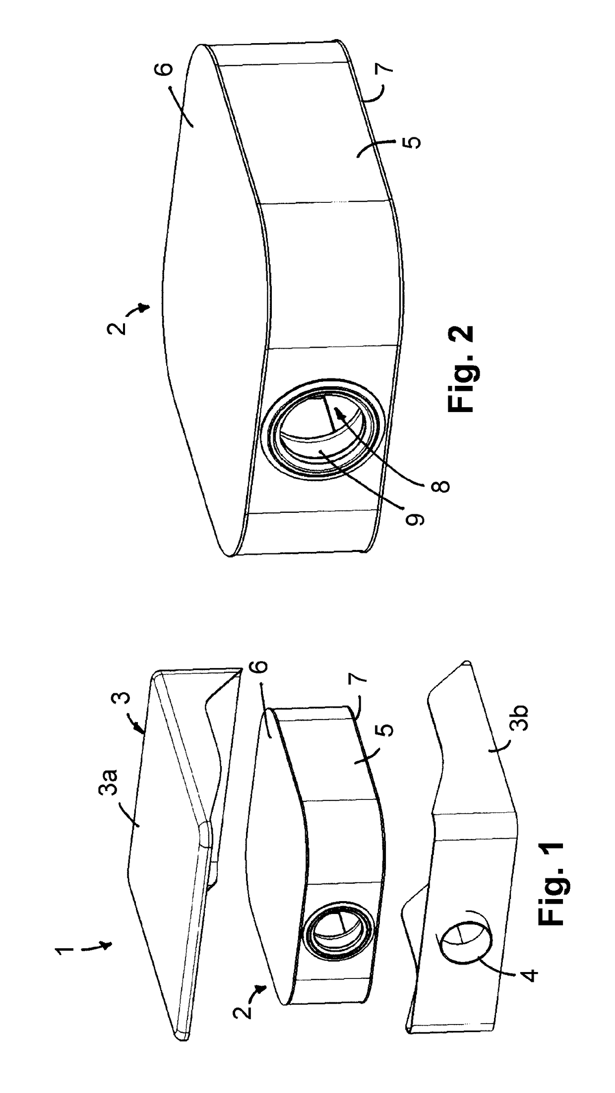
[0033]FIG. 1 shows a filter device 1 for gas filtration. The filter device 1 comprises a filter element 2 and a filter housing 3, which is composed of two housing shells 3a, 3b, which can be assembled to form a closed housing. A flow channel 4 is integrated into the housing shell 3b and is designed in one piece with the housing shell 3b.

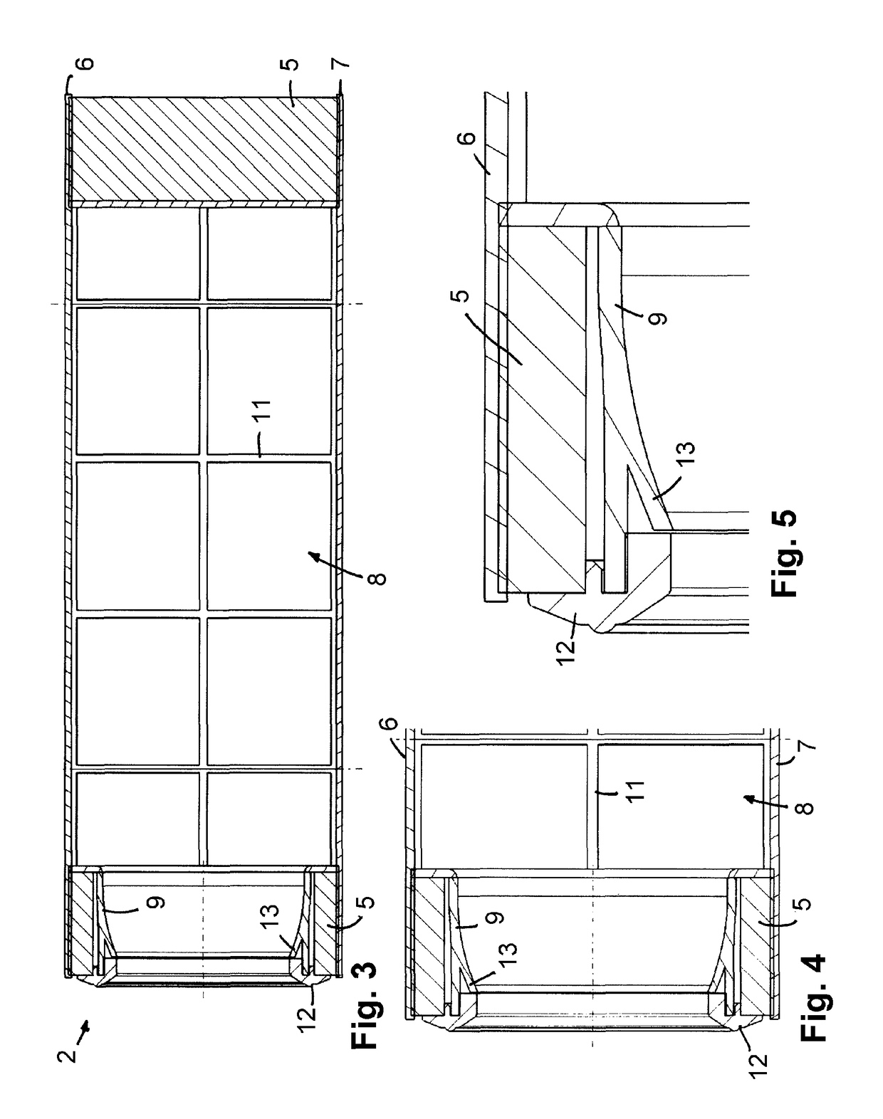
[0034]As is apparent from FIGS. 1 to 5, the filter element 2 comprises an annular filter medium body 5, which encloses an interior flow chamber 8. End caps 6 and 7, which are axially spaced apart from each other and oriented parallel to each other and which axially delimit the flow chamber 8, are located at the end faces of the filter medium body 5. The filter medium body 5 is made of a nonwoven fabric or a paper material, for example, and can be designed as a pleated filter. A carrier connector 9, which completely penetrates the wall of the filter medium body 5 in the radial direction and connects the flow chamber 8 to the surrounding area, is intr...


PUM

PropertyMeasurementUnit
compositionaaaaaaaaaa
distanceaaaaaaaaaa
heightaaaaaaaaaa

Abstract

A filter element has a curved filter medium body, which at least partially encloses a flow chamber, and a carrier connector that is guided through the filter medium body. The carrier connector is a carrier of a sealing element for sealing the contact with a flow channel, wherein a section of the sealing element is arranged between the carrier connector and the filter medium body.

Description

TECHNICAL FIELD[0001]The invention relates to a filter element, in particular for gas filtration, according to the preamble of claim 1.BACKGROUND OF THE INVENTION[0002]DE 10 2008 033 044 B3 discloses an annular filter element for a filter device, wherein the fluid to be purified can flow through the filter element radially from the outside to the inside, so that the enclosed inner flow chamber forms the clean side. A radially extending flow channel, by way of which the purified fluid is discharged from the enclosed flow chamber to the outside, is introduced into the wall of the filter medium body of the filter element which is designed as a pleated filter.[0003]Reference is also made to DE 10 2010 041 657 A1 and EP 2 152 385 B1 with regard to the additional prior art.SUMMARY[0004]It is the object of the invention to create a filter element that has a simple design and comprises a curved filter medium body, wherein the flow chamber enclosed by the filter medium body is provided in a ...

Claims


Application Information

Patent Timeline
Patent Type & Authority Patents(United States)
IPC IPC(8): B01D46/00B01D46/24B01D46/10
CPCB01D46/0005B01D46/2403B01D46/103B01D2271/02
Inventor HASENFRATZ, ROBERTWAGNER, FABIANROESGEN, ANDRETHALMANN, CHRISTIANPFLUEGER, FRANKWITTMERS, CHRISTOPH
Owner MANN HUMMEL GMBH
Why Eureka
Try Eureka