[0010] In the interest of improving ease of operation, the
biopsy device should also feature as a compact a design as possible and, as a hand-held device, should allow for easily moveable single-hand operation, if necessary, so that a single operator can perform the tissue removal process with one hand. In the same
vein, the biopsy device should be designed as an autonomously operating hand-held instrument, the operation of which does not require any external control or supply units that would require connecting lines connected to the hand-held device. This applies, in particular, to the avoidance of a connecting line to an external vacuum source and / or power supply. Moreover, the pressure source with which the generation of a vacuum is preferably to be achieved should be designed to be as simple as possible and should operate reliably. If possible, the removal of tissue samples should occur in such a way that the user, in most cases a pathologist, can be provided with a non-drilled and undamaged
tissue sample for evaluation. Finally, the biopsy device should be inexpensive and should allow for a cost-efficient solution with respect to replaceable
biopsy needles, which are to be viewed as disposable material.
[0016] Using the biopsy device designed in accordance with the invention, it is possible to perform a fully autonomous
tissue sample removal process which, moreover, can be performed by a physician in connection with single-handed operation. All procedures needed to remove a tissue sample take place automatically, i.e., without additional manual support, and can each be triggered by individual keystroke verifications on the biopsy device itself.
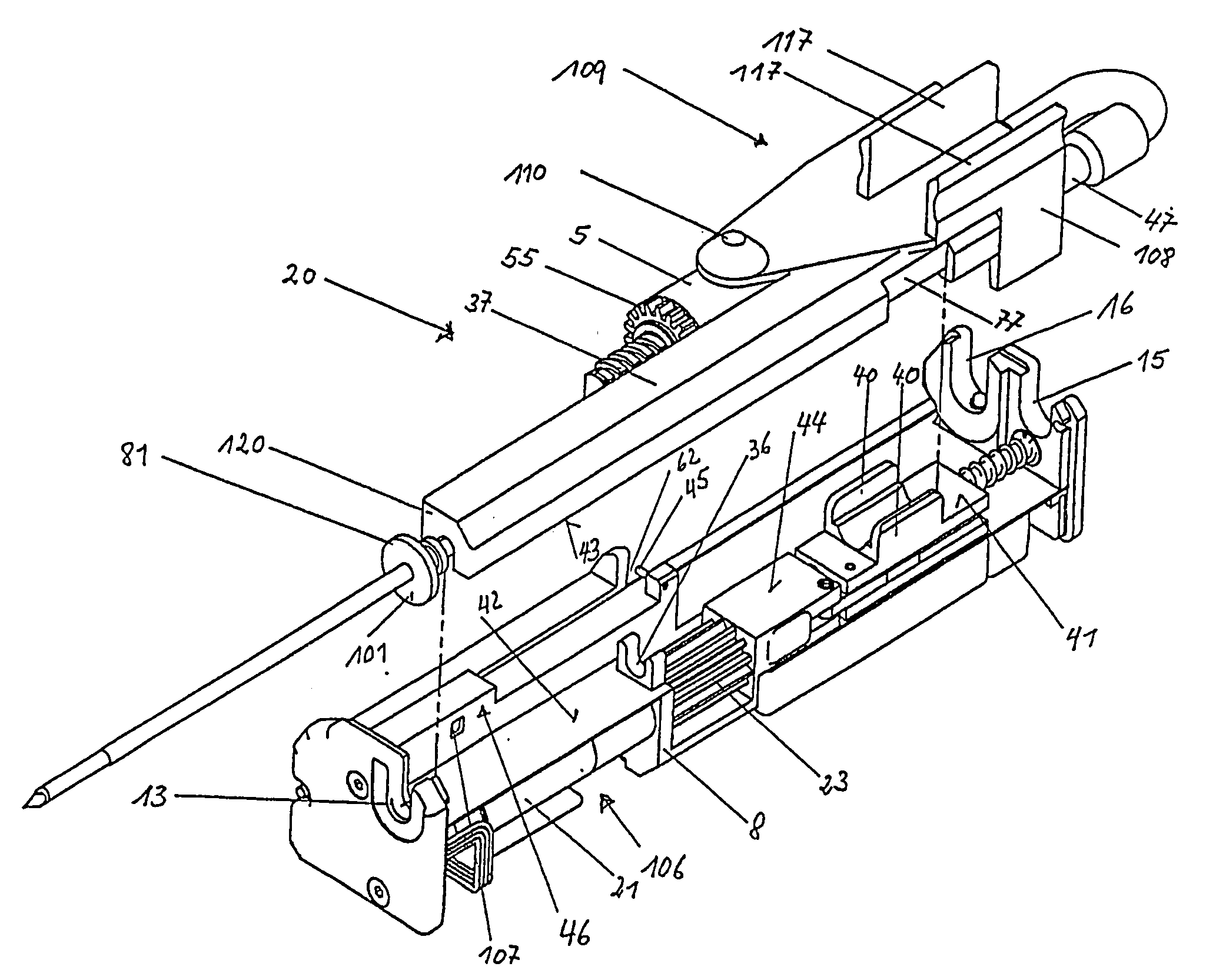
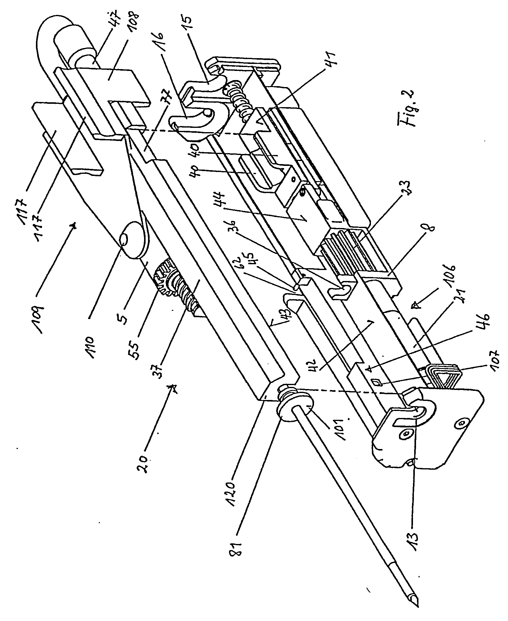
[0017] The individual steps required for complete tissue removal are accomplished by the biopsy device in the following manner: 1) placement of the biopsy needle unit and the clamping cradle into a starting position (this first step is a form of reset function); 2) placement of the clamping cradle into a tensioned state; 3) triggering of a shot, by means of which the biopsy needle unit is distally shot into a tissue region to be examined; 4) automatic development of a vacuum, which can be applied by the pressure source, through the connecting line, along the hollow biopsy needle, and into the tissue removal chamber; 5) tissue severing process, in which the outer hollow needle is shifted proximally and, at the same time, the tissue removal chamber is released under vacuum conditions, which results in surrounding
tissue material being sucked into the tissue removal chamber and being severed from the remaining tissue by the cutting action along the longitudinal edges laterally bordering the tissue removal chamber and configured as cutting edges, wherein the severing process is additionally supported by a periodic distally and proximally directed change in motion of the hollow biopsy cannula, so that, finally, the partially severed tissue sample, which has been sucked into the tissue sample removal chamber, is completely severed by the outer hollow needle being pushed distally forward; and 6) tissue sample removal process, which takes place outside the body, and in which the outer hollow needle proximally releases the tissue sample removal chamber, at least in part, and, due to application of
overpressure through the hollow biopsy needle, especially in the lower region of the tissue sample removal chamber, severing of the tissue sample is brought about, as a result of which the tissue sample is easily removable from the tissue sample removal chamber.
[0018] The procedures described above for careful tissue sample removal can be reliably and safely performed using the biopsy device of the invention. Of particular significance is the fact that the biopsy device is completely independent of external devices supporting the tissue removal process, while at the same providing a high degree of ease of operation, thus easily allowing for single-handed operation. The biopsy device will now be explained in detail while making reference to the exemplary embodiments described below.
[0019] The biopsy device is especially advantageously characterized by the instrument panel to be operated by a treating physician, which is provided in an exterior side wall of the housing of the biopsy device and preferably features only three control keypads, which are installed in an especially clear manner and can be operated completely without error. Thus, for example,
light signal fields are assigned to each control keypad, which provide the physician with information on the current
operability of the individual control keypads and, furthermore, ensure a predetermined completion of functions in accordance with the process described above. Functions that are to be performed with
special care, such as the clamping of the clamping cradle or the operation of the tissue sample removal process, are equipped with a time
delay feature, so that they cannot be triggered inadvertently. The biopsy device is advantageously characterized by these and many other special features, as can be deduced from the following discussion, in which reference is made to the following exemplary embodiments.

