Method of and system for reading visible and/or invisible code symbols in a user-transparent manner using visible/invisible illumination source switching during data capture and processing operations

a technology of user-transparent and visible code symbols, applied in hybrid readers, instruments, sensing record carriers, etc., can solve the problems of more complex systems and costly manufacture than desired, and achieve the effect of avoiding shortcomings and drawbacks

Active Publication Date: 2013-04-02
METROLOGIC INSTR
View PDF25 Cites 793 Cited by
  • Summary
  • Abstract
  • Description
  • Claims
  • Application Information

AI Technical Summary

Benefits of technology

[0009]A primary object of the present disclosure is to provide a new and improved method of and apparatus for reading bar code symbols using either visible or invisible illumination, avoiding the shortcomings and drawbacks of prior apparatus and methodologies.
[0010]Another object of the present invention is to provide a digital imaging based bar code symbol reading system having the capacity to automatically read both visible and invisible bar code symbols in the same application environment, without the complexities and cost presented by prior art techniques and technologies.
[0011]Another object of the present invention is to provide an improved method of automatically reading both visible and invisible bar code symbols in the same application environment, using a single digital imaging device that is simple to manufacture and operate.

Problems solved by technology

While the digital imaging-based and laser-based systems disclosed in these prior art patents possess the capacity to read visible and invisible bar code symbols, in diverse environments, such system are more complex and costly to manufacture than desired in most applications where there is a practical need to read both visible and invisible bar code symbols, but with a greater sense of economy.

Method used


Image

  • Method of and system for reading visible and/or invisible code symbols in a user-transparent manner using visible/invisible illumination source switching during data capture and processing operations
  • Method of and system for reading visible and/or invisible code symbols in a user-transparent manner using visible/invisible illumination source switching during data capture and processing operations
  • Method of and system for reading visible and/or invisible code symbols in a user-transparent manner using visible/invisible illumination source switching during data capture and processing operations

Examples


Embodiment Construction

[0027]Referring to the figures in the accompanying Drawings, the illustrative embodiments of the bar code symbol reading system and method of the present disclosure will be described in great detail, wherein like elements will be indicated using like reference numerals.

Hand-Supportable Digital-Imaging Bar Code Symbol Reading System of the Illustrative Embodiment

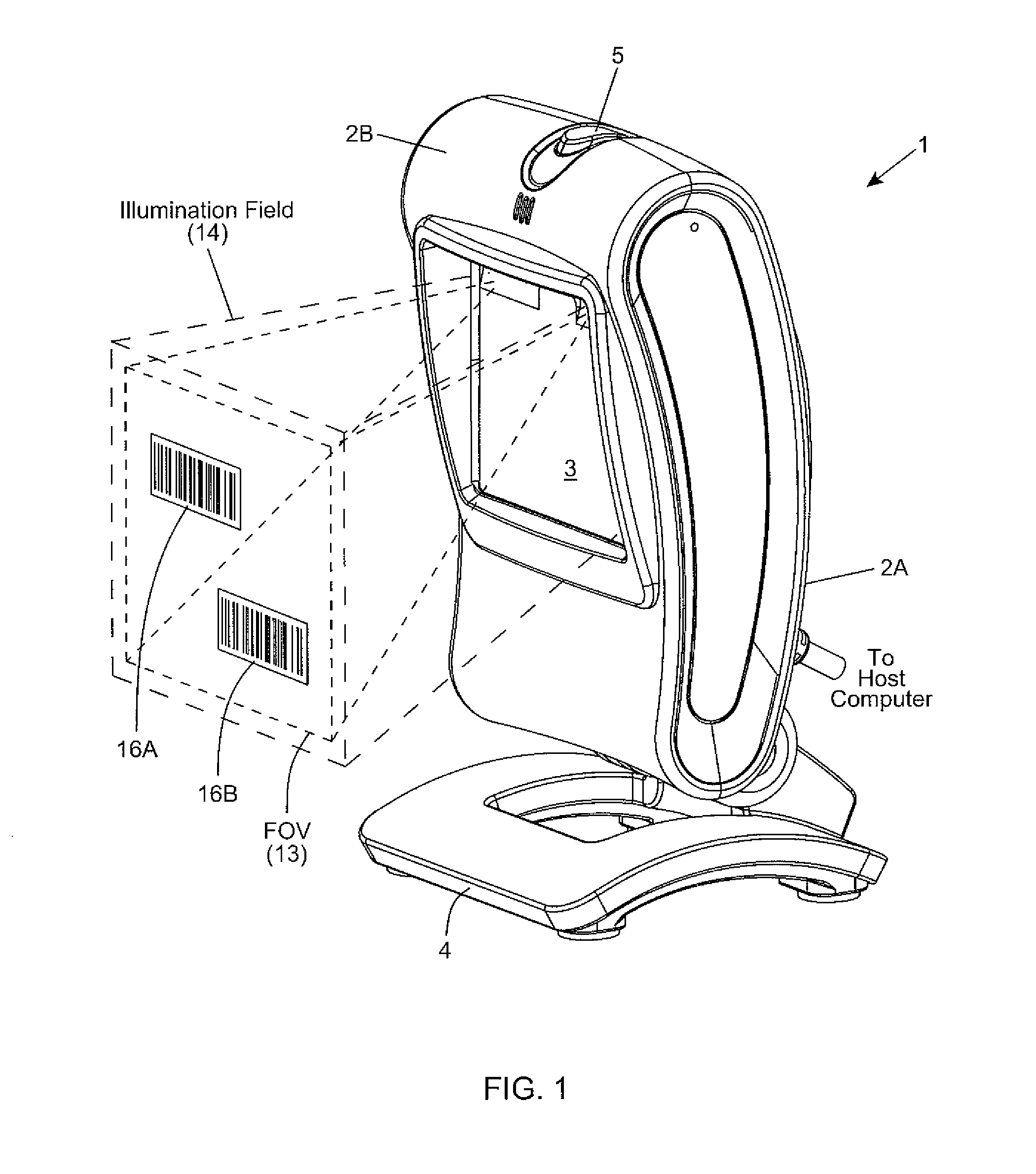
[0028]Referring now to FIGS. 1 through 3, an illustrative embodiment of the hand-supportable digital-imaging bar code symbol reading system 1 will be described in detail.

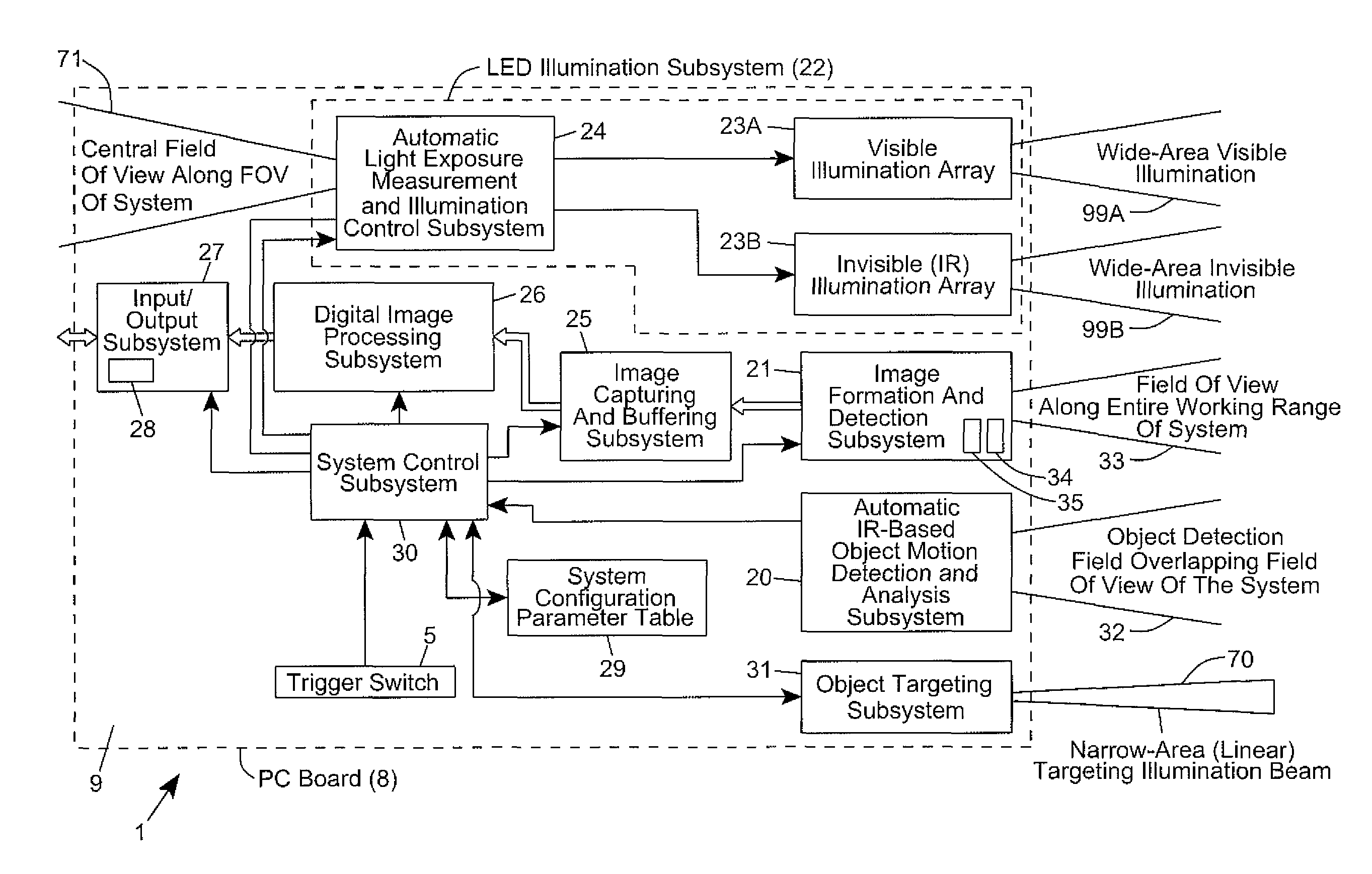
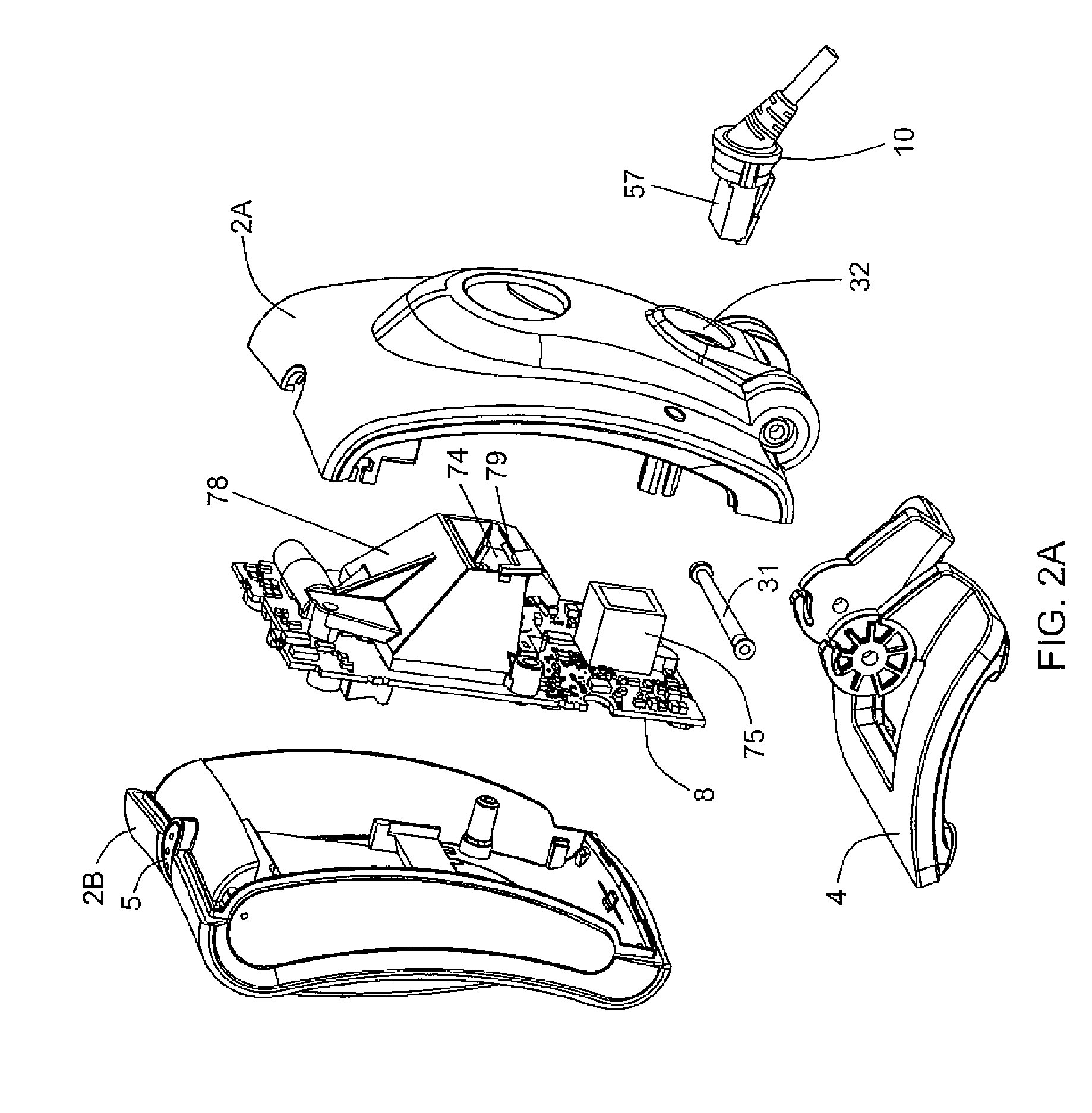
[0029]As shown in FIGS. 1, 2 and 2B, the digital-imaging bar code symbol reading system of the illustrative embodiment 1 comprises: a hand-supportable housing 2 having (i) a front housing portion 2B with a window aperture 6 and an imaging window panel 3 installed therein; and (ii) a rear housing portion 2A. As shown, a single PC board based optical bench 8 (having optical subassemblies mounted thereon) is supported between the front and rear housing portions ...


PUM


Abstract

Method of and system for reading visible and / or invisible code symbols in a user-transparent manner using visible / invisible illumination switching during data capture and processing operations.

Description

BACKGROUND[0001]1. Field of Disclosure[0002]The present disclosure relates to new and improved methods of and systems for reading bar code symbols using visible and invisible sources of illumination during data capture and processing operations.[0003]2. Brief Description of the State of the Art[0004]Today, bar code symbols and labels are used in diverse applications. Typically, a bar code label is printed on a light reflective substrate (e.g. paper) with an ink that is absorptive in the visible-band portion of the electromagnetic spectrum. In such applications, the bar code symbol reader must have a visible source of light (e.g. VLD or visible LED) for reading the visible bar code symbols.[0005]However, in many security-type applications, where access and admission cards and tickets are given out, the security cards bear bar code symbols that are printed with infra-red inks, i.e. inks that reflect only light in the infra-red band portion of the electromagnetic spectrum. In such spec...

Claims


Application Information

Patent Timeline
Patent Type & Authority Patents(United States)
IPC IPC(8): G06K7/10
CPCG06K7/10574G06K7/10584G06K7/10732G06K7/12G06K7/1404G06K7/0004G06K7/10821G06K2207/1012G06K2207/1018G06K2207/1011
Inventor VAN HORN, ERIKKEARNEY, SEAN PHILIP
Owner METROLOGIC INSTR
Why Eureka
Try Eureka