Method of and system for profile equalization employing visible laser diode (VLD) displacement

a technology of visible laser diodes and profiles, applied in the field of profile equalization using visible laser diodes, can solve the problems of large, heavy and expensive, and the balance of output illumination power is simply wasted in the form of heat, and the cost of such scanning devices is increased. size and weight, and the effect of increasing the size and weight of the scanning devi

Inactive Publication Date: 2008-07-08
METROLOGIC INSTR
View PDF42 Cites 3 Cited by
  • Summary
  • Abstract
  • Description
  • Claims
  • Application Information

AI Technical Summary

Benefits of technology

[0013]Accordingly, a primary object of the present invention is to provide an improved method of and system for illuminating the surface of objects during image formation and detection operations and also improved methods of and systems for producing digital images using such improved object illumination, while avoiding the shortcomings and drawbacks of prior art systems and methodologies.
[0014]Another object of the present invention is to provide an improved method of and system for equalizing the power density produced by a linear array of laser light emitting devices, while avoiding the shortcomings and drawbacks of prior art systems and methodologies.

Problems solved by technology

Most prior art CCD-based image scanners, employed in conveyor-type package identification systems, require high-pressure sodium, metal halide or halogen lamps and large, heavy and expensive parabolic or elliptical reflectors to produce sufficient light intensities to illuminate the large depth of fields supported by such industrial scanning systems.
The balance of the output illumination power is simply wasted in the form of heat.
However, even with such improvements in LED illumination techniques, the working distance of such hand-held CCD scanners can only be extended by using more LEDs within the scanning head of such scanners to produce greater illumination output there from, thereby increasing the cost size and weight of such scanning devices.
Similarly, prior art “hold-under” and “hands-free presentation” type CCD-based image scanners suffer from shortcomings and drawbacks similar to those associated with prior art CCD-based hand-held image scanners.
However, there may be situations in which controlling the laser line width is insufficient to achieve complete equalization of the illumination profiles.
Depending on the constraints of the application, it may not be possible to achieve the desired laser line widths at the necessary distances from the image scanner.

Method used


Image

  • Method of and system for profile equalization employing visible laser diode (VLD) displacement
  • Method of and system for profile equalization employing visible laser diode (VLD) displacement
  • Method of and system for profile equalization employing visible laser diode (VLD) displacement

Examples


Embodiment Construction

[0045]Referring to the figures in the accompanying drawings, the preferred embodiments of the method of and system for profile equalization employing visible laser diode (VLD) displacement of the present invention will be described in great detail, wherein like elements will be indicated using like reference numerals.

1. Overview of the Planar Laser Illumination and Electronic Imaging (PLIIM) System of the Present Invention:

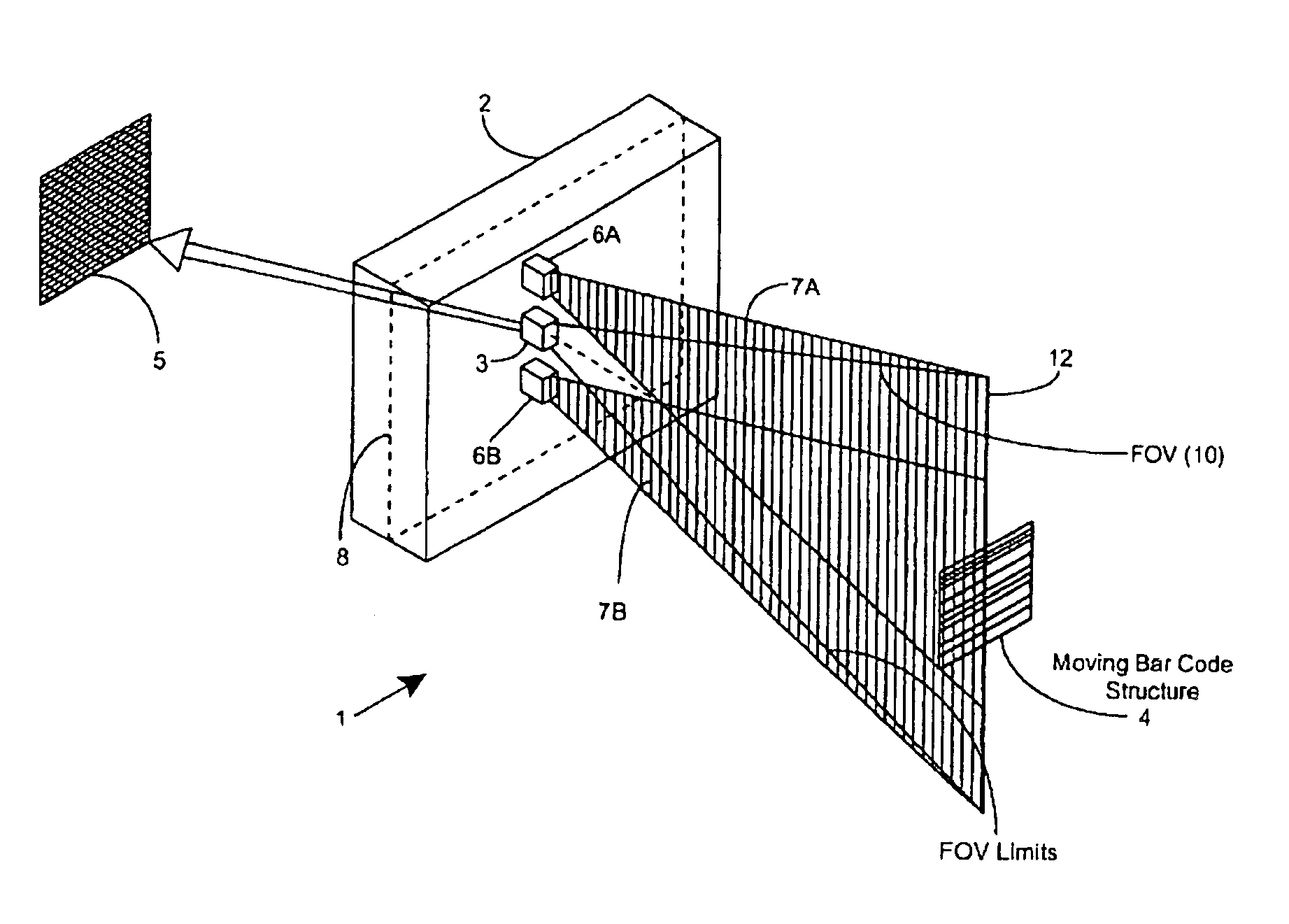
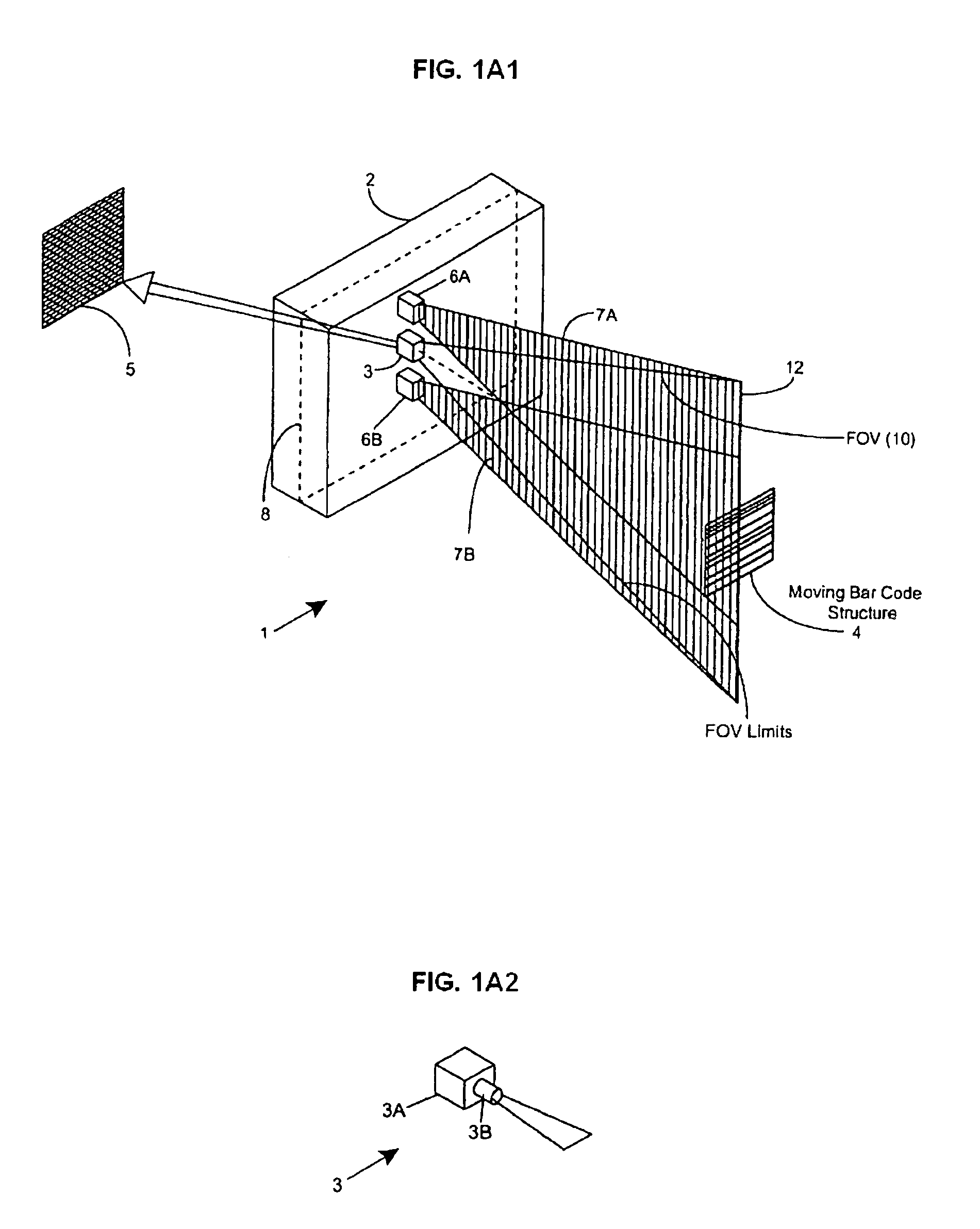
[0046]In accordance with the principles of the present invention, an object (e.g. a bar coded package, textual materials, graphical indicia, etc.) is illuminated by a substantially planar laser illumination beam having substantially-planar spatial distribution characteristics along a planar direction which passes through the field of view (FOV) of an image formation and detection module (e.g. realized within a CCD-type digital electronic camera, or a 35 mm optical-film photographic camera), while images of the illuminated object are formed and detected by the imag...


PUM


Abstract

A method of equalizing the illumination produced by a planar laser illumination array within a planar laser illumination and (electronic) imaging system, comprising the steps of: providing an image formation and detection module having imaging optics with a field of view (FOV) focused upon an image detecting array; providing a planar laser illumination array having a plurality of planar laser illumination modules, each planar laser illumination module producing a planar laser beam component during image formation and detection operations, which are combined to produce a composite planar laser illumination beam extending through a working range of said FOV, wherein said working range includes both near and far fields, if the near field illumination is brighter then the far field illumination: displacing a first portion of the planar illumination modules in a first direction perpendicular to said FOV and a second portion of the planar illumination modules in a second direction opposite to said first direction, angling each planar laser illumination beam component to overlap at said far field, whereby the power density incident on the near field is reduced; and if the far field illumination is brighter then the near field illumination: displacing a first portion of the planar illumination modules in a first direction perpendicular to the FOV and a second portion of the planar illumination modules in a second direction opposite to said first direction, angling each planar laser illumination beam component to overlap at the near field, whereby the power density incident on the far field is reduced.

Description

[0001]This application claims the benefit of U.S. Provisional Patent Application having Ser. No. 60 / 678,884, filed on May 6, 2005, which is hereby incorporated by reference. This application is a continuation-in-part of patent application Ser. No. 10 / 639,362, filed on Aug. 12, 2003, now U.S. Pat. No. 7,143,943, which is a continuation of patent application Ser. No. 09 / 780,027, filed on Feb. 9, 2001, now U.S. Pat. No. 6,629,641, which is a continuation-in-part of patent application Ser. No. 09 / 721,885, filed on Nov. 24, 2000, now U.S. Pat. No. 6,631,842.BACKGROUND OF THE INVENTION[0002]1. Technical Field[0003]The present invention relates generally to an improved method of and system for profile equalization employing visible laser diode (VLD) displacement during image formation and detection operations, and also to an improved method of and system for producing digital images using such improved object illumination.[0004]2. Brief Description of the Prior Art[0005]The use of image-ba...

Claims


Application Information

Patent Timeline
Patent Type & Authority Patents(United States)
IPC IPC(8): G02B5/00
CPCG02B27/0961G02B27/0966G02B19/0028G02B19/0057G06K7/10732
Inventor KNOWLES, C. HARRYSCHNEE, MICHAELZHU, XIAOXUN
Owner METROLOGIC INSTR
Why Eureka
Try Eureka