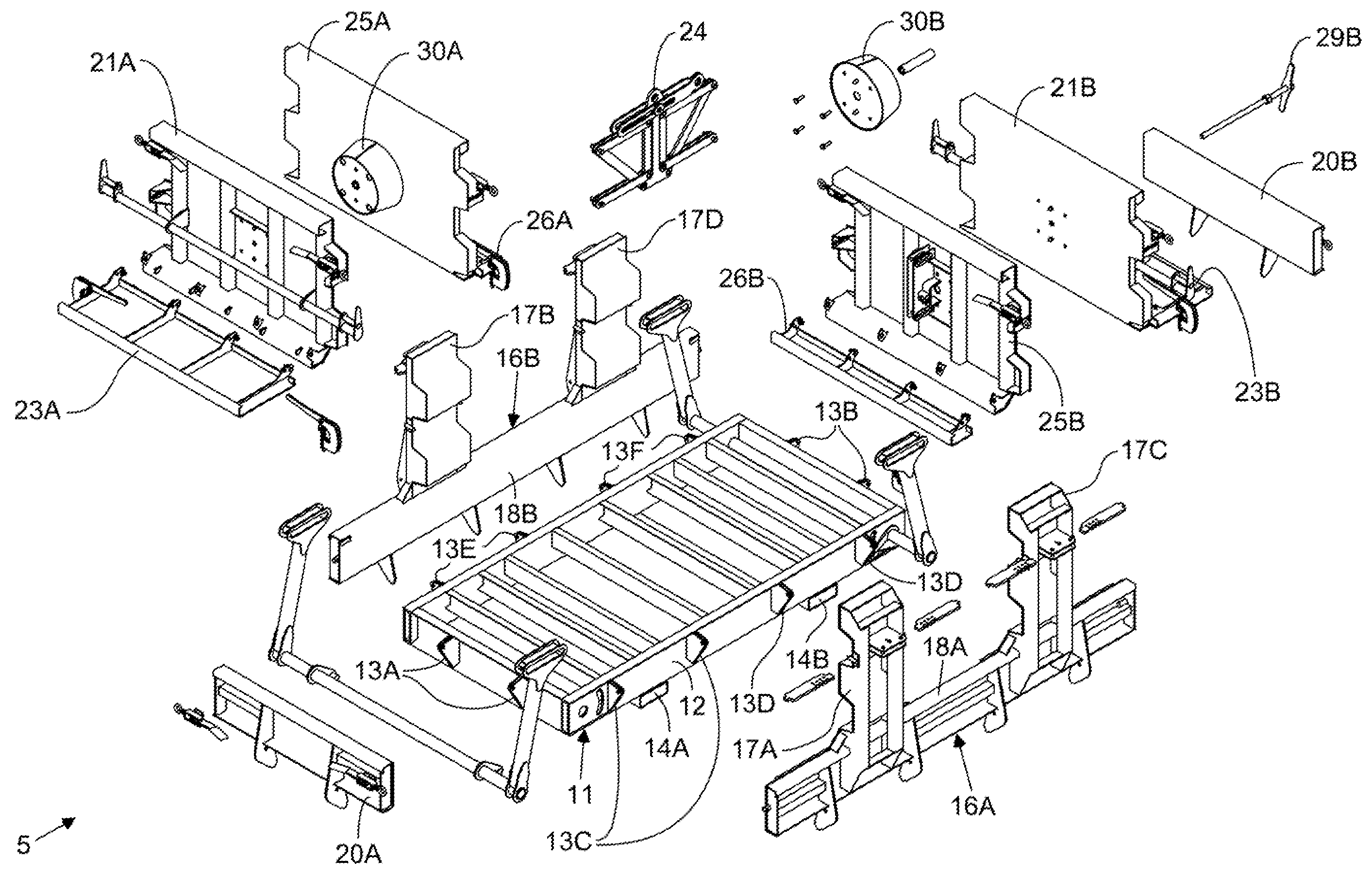
Machine for manufacturing concrete U-wall type construction blocks by molding each concrete U-wall construction block from concrete poured about a block cage made from reinforcing material while said block cage is loaded within said machine

a technology of concrete and construction blocks, which is applied in the direction of dough shaping, manufacturing tools, applications, etc., can solve the problems of large manual labor, high cost and human management, and the inability to meet the needs of workers required to handle molds and forms used in prior art construction procedures, so as to avoid the shortcomings and drawbacks

Active Publication Date: 2014-11-18
STABLE CONCRETE STRUCTURES +1
View PDF46 Cites 8 Cited by
  • Summary
  • Abstract
  • Description
  • Claims
  • Application Information

AI Technical Summary

Benefits of technology

[0016]Accordingly, it is a primary object of the present invention to provide an improved method of and a machine for molding U-wall type wall construction blocks and elements, and a method of operating the same in a high-efficiency manner, while avoiding the shortcomings and drawbacks of prior art methodologies.

Problems solved by technology

While providing a modular construction, such prior art construction blocks and retaining walls, nevertheless suffer from several significant shortcomings and drawbacks.
While the U-wall construction element disclosed in U.S. Pat. No. 5,163,261 has many advantages over the prior art, conventional techniques for manufacturing this U-wall construction block suffer from a number of significant shortcomings and drawbacks.
Conventional methods of U-wall block manufacture require large amounts of manual labor which is expensive and requires costly human management.
Conventional methods of U-wall block manufacture also creates unnecessary risks to workers required to handle the molds and forms used during prior art constructing procedures.

Method used


Image

  • Machine for manufacturing concrete U-wall type construction blocks by molding each concrete U-wall construction block from concrete poured about a block cage made from reinforcing material while said block cage is loaded within said machine
  • Machine for manufacturing concrete U-wall type construction blocks by molding each concrete U-wall construction block from concrete poured about a block cage made from reinforcing material while said block cage is loaded within said machine
  • Machine for manufacturing concrete U-wall type construction blocks by molding each concrete U-wall construction block from concrete poured about a block cage made from reinforcing material while said block cage is loaded within said machine

Examples


Embodiment Construction

which is to be taken in connection with the accompanying Drawings, wherein:

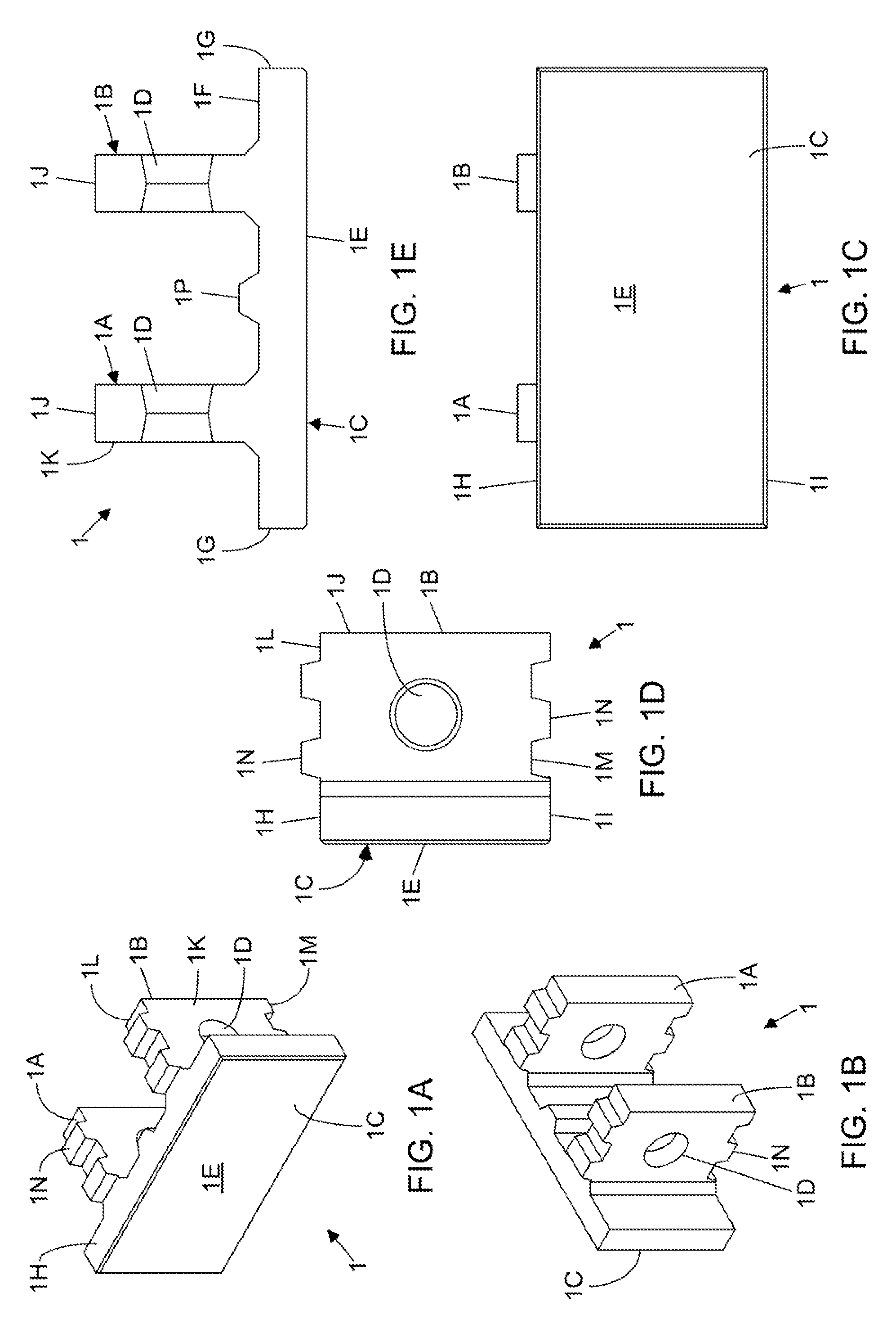
[0034]FIG. 1A is a front perspective view of a U-shaped retaining wall construction element (“U-wall construction block”) showing it pair of anchor arms protruding from the front wall panel;

[0035]FIG. 1B is a rear perspective view of a U-shaped retaining wall construction element showing it pair of anchor arms protruding from the fear side of the front wall panel;

[0036]FIG. 1C is a front elevated view of the front wall portion of the U-shaped retaining wall construction element shown in FIG. 1A;

[0037]FIG. 1D is an elevated side view of the U-shaped retaining wall construction element shown in FIG. 1A;

[0038]FIG. 1E is a plan cross-sectional view of the U-shaped retaining wall construction element shown in FIG. 1A, showing the circular aperture formed in each anchor arm of the construction element;

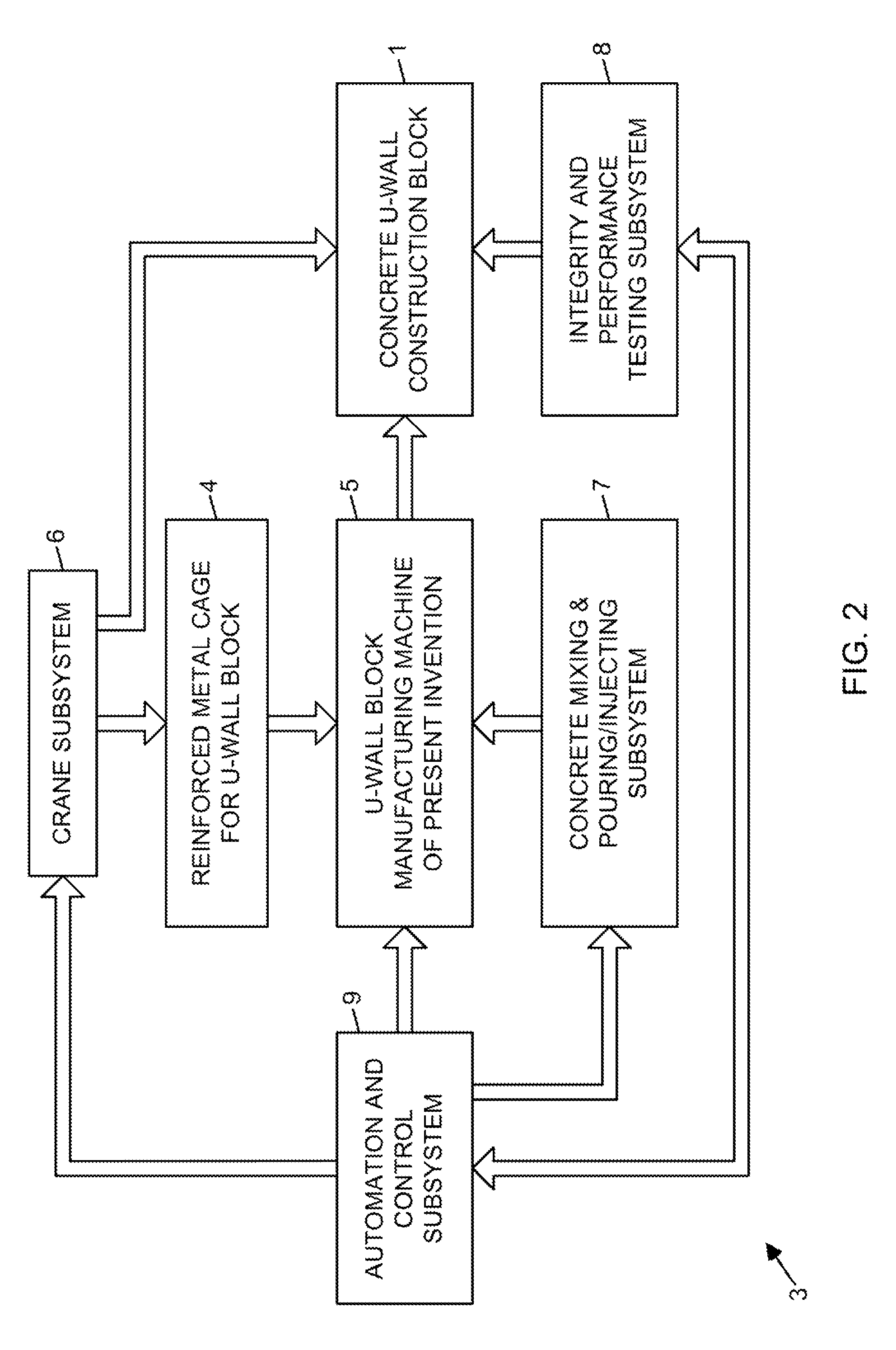
[0039]FIG. 2 is a schematic system block diagram showing the components of the automated U-wall construction block ...


PUM

PropertyMeasurementUnit
heightaaaaaaaaaa
dimensionsaaaaaaaaaa
moldingaaaaaaaaaa

Abstract

A machine for and method of manufacturing concrete U-wall construction blocks, each having a front wall portion and a pair of stem portions extending from said front wall portion. The method involves providing a system of molding jacket panels, including a core molding assembly having a pair of inside stem jacket panels that are adjustably supportable in a substantially parallel manner during a molding process, and arranged is such a manner that the front wall portion is molded in downwardly facing direction toward a horizontal support surface and completely enclosed in one or more molding jacket panels. Before block molding operations, the thickness of the front wall portion of the U-wall construction block is set by determining the thickness of a front wall surface liner and installing the front wall surface forming liner within the system of molding jacket panels. Also, thickness of the stem portions of the U-wall construction block is set by determining the proper distance between the pair of said inside stem jacket panels supported in a parallel manner during the block molding process. Thereafter, concrete is poured or injected through pour openings provided in the molding jacket apparatus to form the front wall portion and stem portions of the concrete U-wall block.

Description

BACKGROUND OF THE INVENTION[0001]1. Field of the Invention[0002]The present invention relates to an improved method of and machine for manufacturing U-wall type construction elements for building soil retaining walls and the like, and a method of operating the same with improved levels of efficiency.[0003]2. Brief Description of Related Art[0004]Retaining walls are widely used in a variety of architectural and site development applications including, for example, office developments, commercial complexes, industrial sites, residential developments, waterfront and coastal structures, and highway cut and fill areas. In such applications, it is not uncommon for the height of retaining walls to exceed 20 feet or more. In nearly all applications, such retaining walls must provide stability against pressures exerted by back fill soil and heavy surcharge loads, and thus be self-supporting.[0005]Self-supporting retaining wall systems are well known.[0006]One popular construction block for s...

Claims


Application Information

Patent Timeline
Patent Type & Authority Patents(United States)
IPC IPC(8): B28B7/04B28B13/04B28B7/00B28B7/30
CPCB28B7/0029B28B13/04B28B7/0044B28B7/10
Inventor O'NEILL, RAYMONDCARR, DENNIS
Owner STABLE CONCRETE STRUCTURES
Why Eureka
Try Eureka