Operation unit and treatment tool for endoscope provided with the same

a technology for treating tools and endoscopes, which is applied in the field of operation units and treatment tools for endoscopes provided with the same, can solve the problems of large increase in total production costs, difficult visual identification of operation units with fixed rotatable parts, and management's need to prevent the use of operation units. , to achieve the effect of reducing the production cost of treatment tools

Active Publication Date: 2013-06-25
HOYA CORP
View PDF11 Cites 779 Cited by
  • Summary
  • Abstract
  • Description
  • Claims
  • Application Information

AI Technical Summary

Benefits of technology

[0004]There are various types of treatment tools for an endoscope. Thus, in order to reduce production costs of the treatment tools, the treatment tools are manufactured with a common operation unit attached thereto.
[0005]Additionally, it is considered to achieve a further cost reduction by putting, into a common configuration, an operation unit adapted such that a flexible sheath is joined rotatably to an operation unit body and an operation unit adapted such that a flexible sheath is joined to an operation unit body in an un-rotatable manner.
[0008]Aspects of the present invention are advantageous to provide one or more improved operation units of treatment tools for an endoscope that can easily be used commonly for both types of a flexible sheath joined rotatably to an operation unit body and a flexible sheath joined to an operation unit body in an un-rotatable manner, with little expense and concern about misuse of the operation units.
[0009]According to aspects of the present invention, an operation unit of a treatment tool for an endoscope is provided, which includes a first joining member configured to be joined to a rear end of a flexible sheath of the treatment tool, a second joining member configured such that the first joining member is fitted therearound rotatably around a first axis line of the first joining member relative to the second joining member, and a pin fit hole formed between the first joining member and the second joining member such that a pin is fitted therein, the pin fit hole being configured to restrict rotational movement of the first joining member around the first axis line relative to the second joining member when the pin is fitted in the pin fit hole.
[0010]Optionally, the first joining member may be fitted around the second joining member so as to restrict movement of the first joining member in a direction along the first axis line relative to the second joining member.

Problems solved by technology

It results in a serious increase in a total production cost (for example, a cost increase by several tens of yen up to more than a hundred yen).
Furthermore, it is difficult to visually distinguish the operation unit with the rotatable portion fixed with the bonding material from the operation unit with the rotatable portion not fixed.
Therefore, a lot of efforts are required for management to prevent the operation units from being mistakenly used.

Method used


Image

  • Operation unit and treatment tool for endoscope provided with the same
  • Operation unit and treatment tool for endoscope provided with the same
  • Operation unit and treatment tool for endoscope provided with the same

Examples


Embodiment Construction

[0029]It is noted that various connections are set forth between elements in the following description. It is noted that these connections in general and, unless specified otherwise, may be direct or indirect and that this specification is not intended to be limiting in this respect.

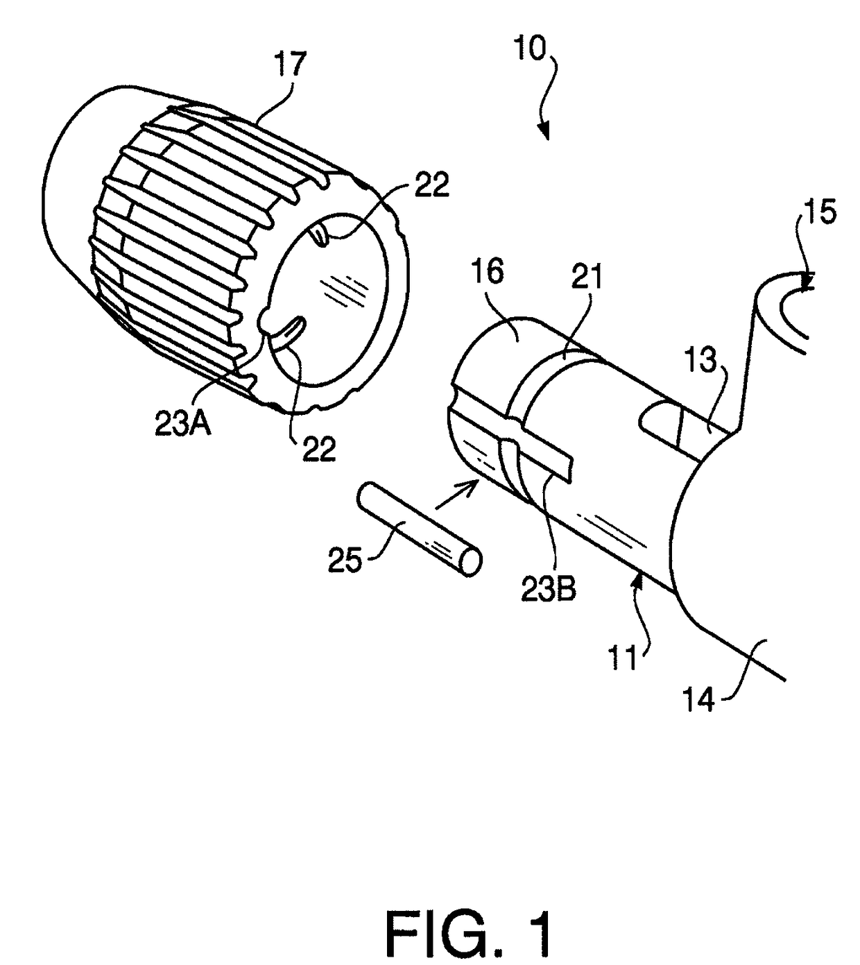
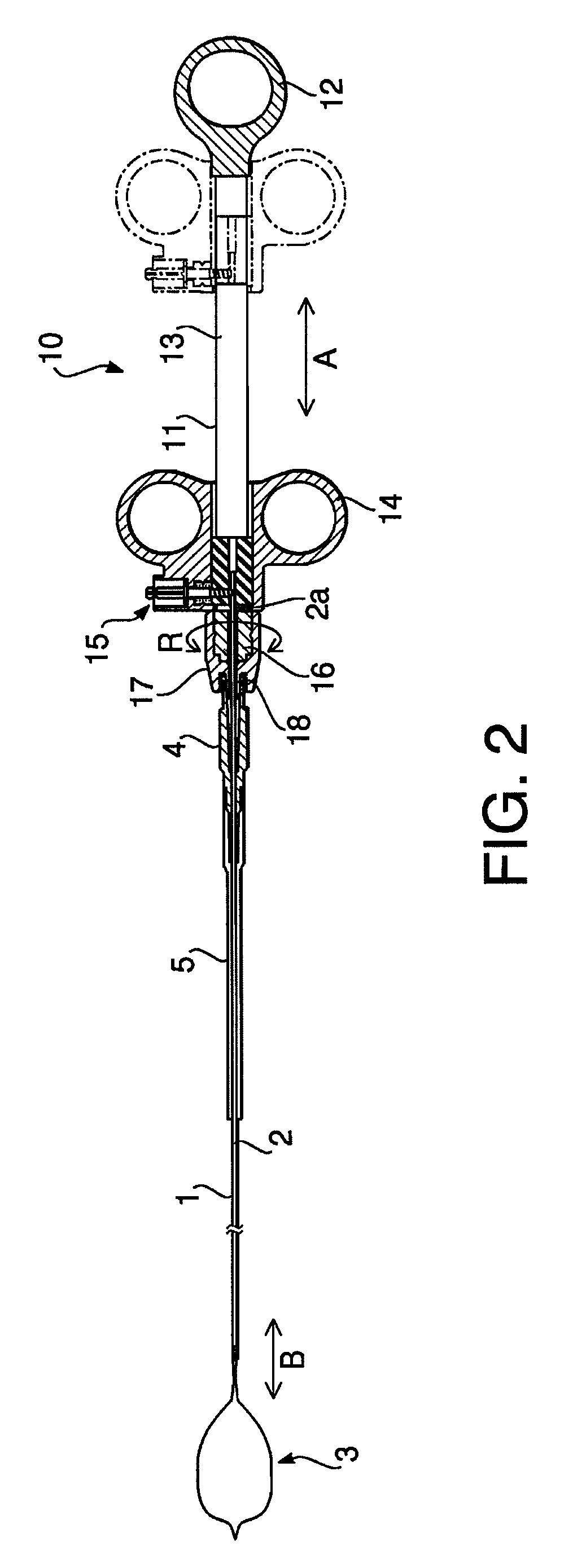
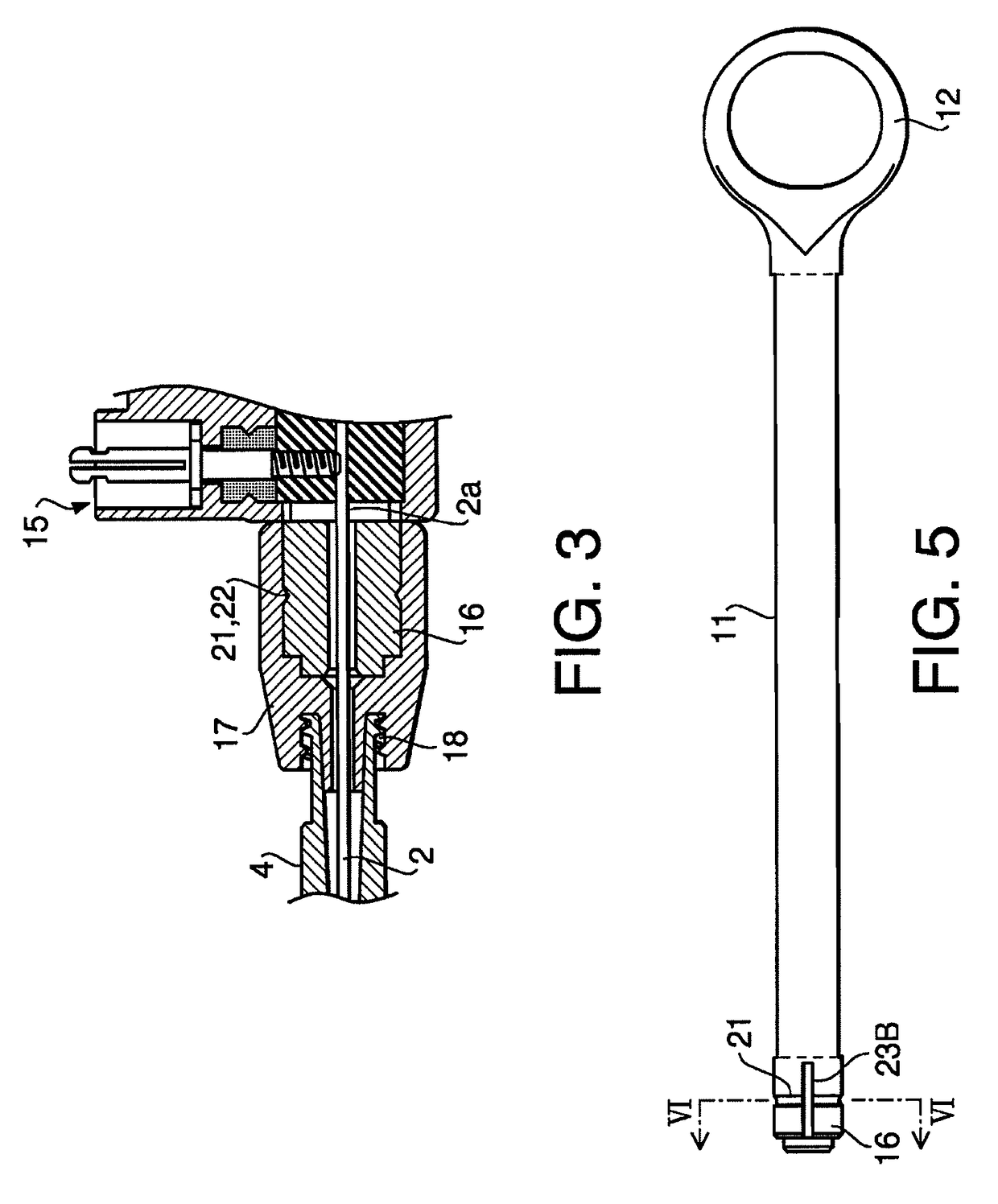
[0030]Hereinafter, an embodiment according to aspects of the present invention will be described with reference to the accompanying drawings. FIG. 2 shows a high frequency snare as one of treatment tools for an endoscope. A flexible sheath 1 is configured to be inserted into and pulled out of a treatment tool insertion channel (not shown) of an endoscope. In the flexible sheath 1, an electrically conductive operation wire 2 is inserted so as to move back and forth in the direction along the axis line of the flexible sheath 1 and to rotate around the axis line. Further, a snare loop as a distal end treatment member 3 is joined to the distal end of the operation wire 2 so as to protrude and recede from the...


PUM


Abstract

An operation unit of a treatment tool for an endoscope includes a first joining member configured to be joined to a rear end of a flexible sheath of the treatment tool, a second joining member configured such that the first joining member is fitted therearound rotatably around an axis line of the first joining member relative to the second joining member, and a pin fit hole formed between the first joining member and the second joining member such that a pin is fitted therein, the pin fit hole being configured to restrict rotational movement of the first joining member around the axis line relative to the second joining member when the pin is fitted in the pin fit hole.

Description

BACKGROUND OF THE INVENTION[0001]The following description relates to one or more operation units of a treatment tool for an endoscope.[0002]An operation unit of a treatment tool for an endoscope is in general configured such that a wire operating member is provided slidably relative to an operation unit body. Here, the wire operating member is configured to move an operation wire back and forth in a flexible sheath in the axis line direction of the operation wire, from the rear end of the operation unit, (for example, see Japanese Patent Provisional Publication No. 2004-261372).[0003]In addition, there is a type of treatment tool having a conveniently improved operation unit which is configured such that a flexible sheath is joined to an operation unit body rotatably around the axis line of the flexible sheath (for example, see Japanese Utility Model Provisional Publication No. SHO61-18885).SUMMARY OF THE INVENTION[0004]There are various types of treatment tools for an endoscope. T...

Claims


Application Information

Patent Timeline
Patent Type & Authority Patents(United States)
IPC IPC(8): A61B17/00
CPCA61B18/1482A61B17/32056A61B2017/0046A61B2017/00477A61B2017/2911A61B2017/292A61B2018/1407
Inventor SUGITA, NORIYUKI
Owner HOYA CORP
Why Eureka
Try Eureka