Solar energy utilization unit and solar energy utilization system

a solar energy and solar energy technology, applied in the field of solar energy utilization systems, can solve problems such as the tendency to lose reflection abilities, and achieve the effect of minimizing the deterioration of quality

Inactive Publication Date: 2005-03-03
AEROSUN TECH
View PDF17 Cites 208 Cited by
  • Summary
  • Abstract
  • Description
  • Claims
  • Application Information

AI Technical Summary

Benefits of technology

[0021] heat removal from the radiation receiving portions of the receiver component is better manageable, since each receiving portion is only getting the part of the radiation spectrum applicable to it.
[0022] The solar energy utilization unit of the present invention may further comprise a rigid cover firmly and sealingly attached to the primary reflector, along the circumference of the latter, thereby forming a closed volume between the cover's inner surface and the inner, reflecting surface of the primary reflector with the solar radiation receiver component secured thereto. The unit may comprise means to control environment of the closed volume for minimizing deterioration of the quality of the reflectors.

Problems solved by technology

Reflectors exposed to the environment for extended periods, tend to lose their reflection abilities due to, for example, dust or sand erosion, oxidation or corrosion.

Method used


Image

  • Solar energy utilization unit and solar energy utilization system
  • Solar energy utilization unit and solar energy utilization system
  • Solar energy utilization unit and solar energy utilization system

Examples


Embodiment Construction

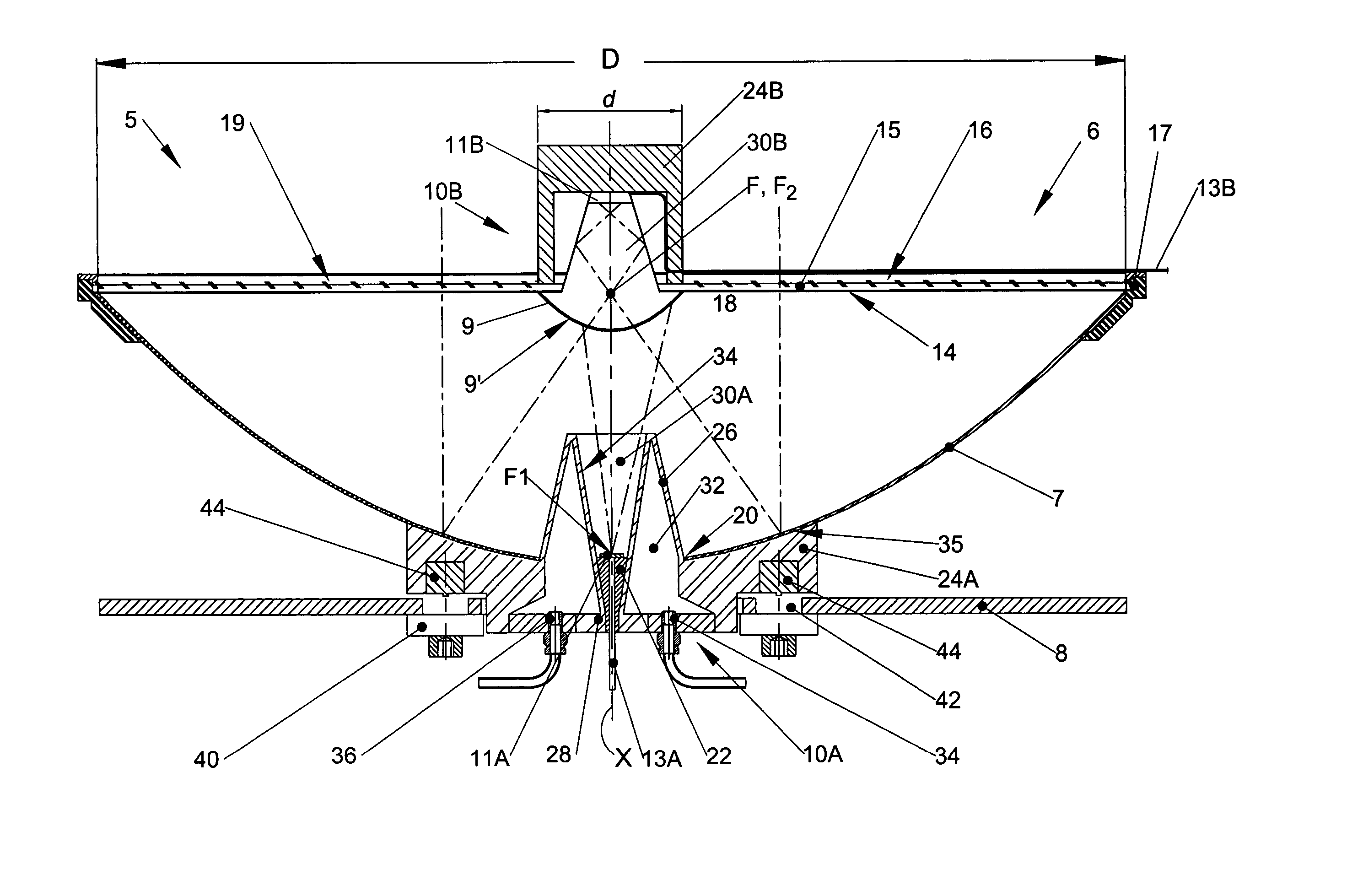
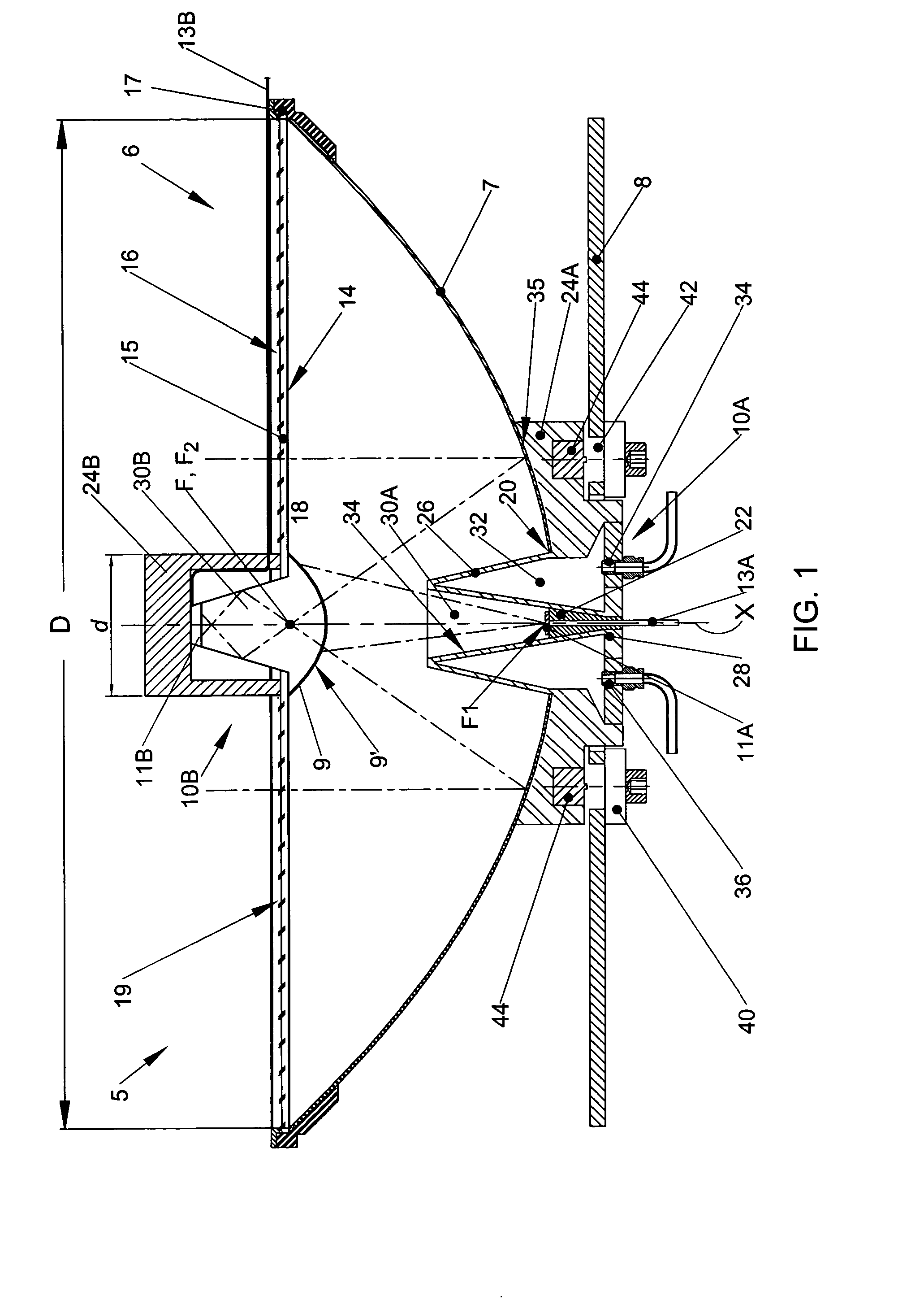
[0031]FIG. 1 shows a solar energy utilization unit 5 in accordance with one embodiment of the present invention. The unit 5 comprises a solar radiation concentrating optics 6 including a concave primary reflector 7 and a convex secondary reflector 9, and a solar receiver designed to convert the radiation concentrated by the optics 6 into electric energy, the solar receiver comprising a first and second photovoltaic receiver components 10A and 10B, each associated with either primary reflector 7 or secondary reflector 9.

[0032] Each receiver component 10A, 10B comprises a photo-voltaic structure 11A, 11B, which may be a singular plate cell or an array of cells. The photo-voltaic structures 11A and 11B have different sensitivity wavebands, e.g. one of them is sensitive to radiation in the IR part of the solar spectrum and the other—in the visible part, and are designed to convert radiation within their corresponding wavebands into electric energy. The structures 11A and 11B are provid...


PUM


Abstract

A solar energy utilization unit comprises a solar radiation concentrating optics and a solar radiation receiver including first and second receiver components. The first receiver component is designed to convert into electric energy radiation in a first part of the solar spectrum, and the second receiver component is designed to convert into electric energy radiation in a second part of the solar spectrum different from said first part. The solar radiation concentrating optics comprises a concave primary reflector and a convex secondary reflector. The primary reflector is adapted to reflect incident solar radiation towards the secondary reflector, the secondary reflector is adapted to reflect radiation in the first part of the solar spectrum into the first receiver component and to transmit radiation in the second part of the solar spectrum into the second receiver component. The primary reflector is formed with a centrally disposed opening via which the first receiver component is adapted to receive the radiation reflected by the secondary receiver.

Description

[0001] This application is a Continuation-in-Part of International Application No. PCT / IL2004 / 000787 filed Aug. 31, 2004.FIELD OF THE INVENTION [0002] This invention relates to the field of solar energy utilization systems and particularly, to such systems using solar radiation concentration optics of the cassegrainian type. BACKGROUND OF THE INVENTION [0003] A standard cassegrainian concentration optics comprises two reflectors, a primary reflector and a secondary reflector, which are coaxially aligned. The primary reflector captures and reflects incoming radiation to the generally smaller secondary reflector. The secondary reflector in turn reflects the radiation toward the focus of the concentration optics associated with a solar receiver. The primary and secondary reflectors may have different shapes, e.g. the primary reflector may be parabolic and the secondary reflector may be hyperbolic. [0004] The solar receiver may be based on direct absorption of the heat of solar radiatio...

Claims


Application Information

Patent Timeline
Patent Type & Authority Applications(United States)
IPC IPC(8): F24S23/71F24S23/79G02B17/06H01L31/052
CPCF24J2/12F24J2/18G02B17/061H01L31/0547Y02B10/20Y02E10/42Y02E10/52H01L31/052H01L31/0521H02S40/425F24S23/71F24S23/79F24S50/20Y02E10/47Y02E10/44Y02E10/40
Inventor SHIFMAN, ELI
Owner AEROSUN TECH
Why Eureka
Try Eureka