Scuff plate

Active Publication Date: 2009-10-08
TOYODA GOSEI CO LTD
View PDF17 Cites 307 Cited by
  • Summary
  • Abstract
  • Description
  • Claims
  • Application Information

AI Technical Summary

Benefits of technology

[0016]In a scuff plate of the present invention, a groove formed in an underside of a first light guide element forms a character section (a letter, a figure, a symbol, and the like). Light from the first light source is guided into the first light guide element, and guided light undergoes reflective diffusion at the character section. As a consequence, a desired character, or the like, is luminously displayed. In the meantime, light generated by the light emission unit exits through the first light guide element, and an area (background) of the plate except the character section is illuminated in color differing from the color of light from the first light source. Thus, the character section and its background are illuminated in two different colors

Problems solved by technology

The surface emitting device is suitable for a simple luminous display, such as a luminous display of a predetermined pattern and a luminous display o

Method used


Image

  • Scuff plate
  • Scuff plate
  • Scuff plate

Examples


embodiment

(Embodiment)

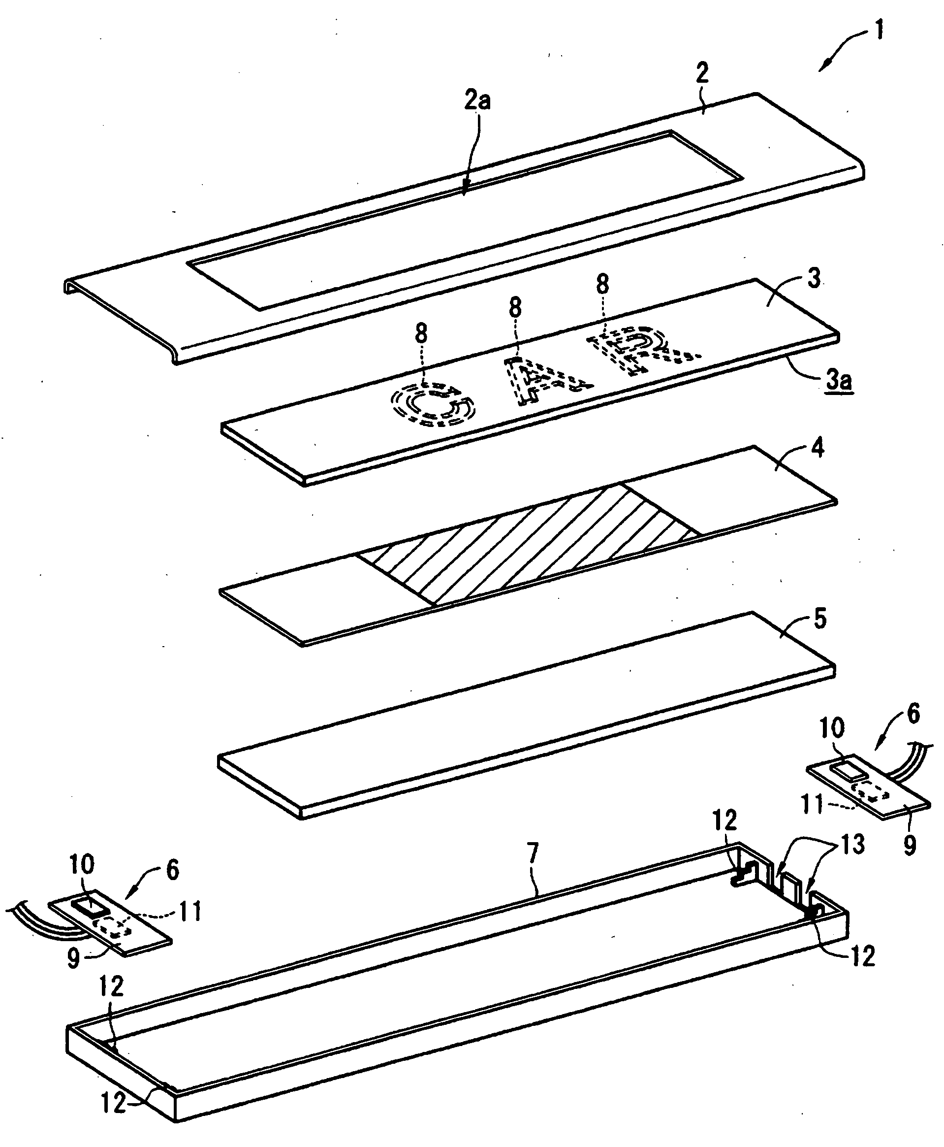
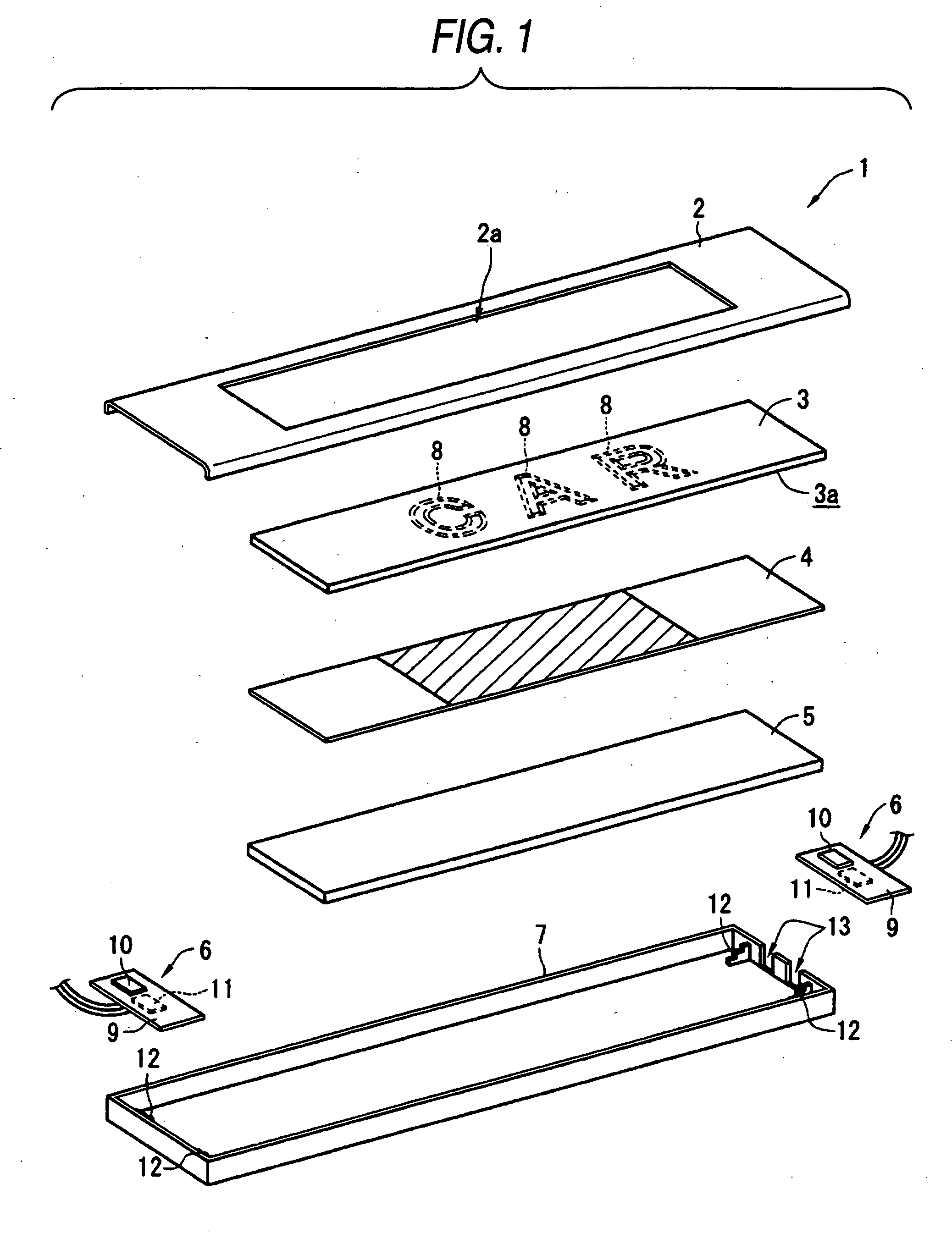
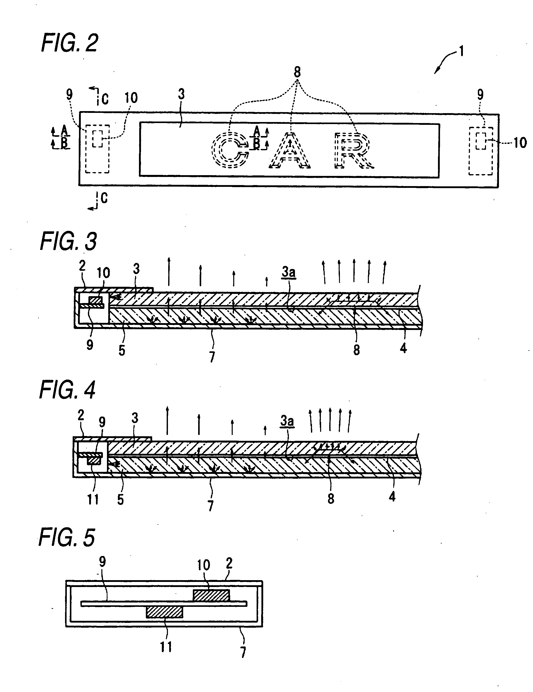
[0045]FIGS. 1 through 5 show a scuff plate 1 that is an embodiment of the present invention. FIG. 1 is an exploded perspective view of the scuff plate 1; FIG. 2 is a plan view of the same; FIG. 3 is a cross-sectional view taken along line A-A shown in FIG. 2; FIG. 4 is a cross-sectional view taken along line B-B; and FIG. 5 is a cross-sectional view taken along line C-C. The configuration of the scuff plate 1 and a display mode of the same are now described hereunder by reference to the drawings.

[0046]The scuff plate 1 is made up of a cover 2, a character plate 3, an optical sheet 4, a light guide plate 5, a pair of light source units 6, and a case 7. The character plate 3, the optical sheet 4, and the light guide plate 5 are housed in the case 7 in a piled manner. When the scuff plate is housed in the case 7, the optical sheet 4 is arranged below the character plate 3, and the light guide plate 5 is arranged below the optical sheet 4. The light source units 6 are housed...


PUM


Abstract

A scuff plate has a first light guide element having a groove of predetermined shape formed in an underside of the element when viewed from below, a first light source that guides light to the first light guide element, light emission unit that is disposed below the first light guide element and that upwardly emits light differing in color from the first light source, and a half mirror layer interposed between the first light guide element and the light emission unit. Light from the first light source is guided to the first light guide element, and the guided light undergoes reflective diffusion at the groove (a character section). As a consequence, a desired character, or the like, is luminously displayed. In the meantime, light generated by the light emission unit exits through the first light guide element, whereupon an area (a background area) other than the groove (the character section) is illuminated in color that differs from the color of light from the first light source.

Description

BACKGROUND OF THE INVENTION[0001]1. Field of the Invention[0002]The present invention relates to a scuff plate that luminously displays a desired shape (a letter, a numeral, and the like).[0003]2. Description of the Related Art[0004]A scuff plate device for use in an automobile that yields a decorative effect by luminously displaying a character, and the like, has been put into practice. FIG. 6 shows an example of a related-art transmission, light-emitting scuff plate device 100. In the scuff plate device 100, a character plate 101 (e.g., an aluminum plate) punched into the shape of a desired character, and the like, is piled on a light guide plate 102. An underside of the light guide plate 102 is printed in white. A light source 103 is positioned at a place opposite an end face of the light guide plate 102. When the light source 103 is illuminated in such a scuff plate device 100, light is guided into the light guide plate 102 by way of its end face. The thus-guided light undergoes...

Claims


Application Information

Patent Timeline
IPC IPC(8): F21V7/22
CPCB60Q1/323B60R13/04G02B6/0021B60R2013/046G02B6/0086G09F13/18G02B6/005B60Q1/325
Inventor KINO, NORIHITOINAGAKI, SATOSHI
Owner TOYODA GOSEI CO LTD
Why Eureka
Try Eureka