However, it is very difficult to manufacture cabinet panels and switch boards.
Therefore, manufacturing costs are increased and a
delay in delivery is generated since it is possible to manufacture cabinet panels and switch boards only by a
bus bar processor.
Therefore, there is always a danger of accidents.
Also, since a location of a breaker connected to right and left of a branch breaker is out of line in a conventional
bus bar connection way, which makes it impossible to fix an each phase, it is impossible to allow right and left branch breakers to correspond to each other by embodying a highly wrought connection bus bar.
Also, since there is required a lot of time to manufacture a cabinet panel, it is difficult to quickly restore an emergent electric accident.
Also, when disassembling a cabinet panel or a switch board, it is difficult to recycle components since components are not standardized.
However, in this case, a
toxic gas is generated from acryl on fire.
Also, the charger is exposed when checking or changing a breaker, thereby generating electric shocks and short-circuits due to foreign substances.
However, general block type power distribution apparatuses have problems as below.
However, there occurs a case where a certain breaker cannot be used because a height of a block type power distribution apparatus is different from that of a branch breaker.
However, there is required another additional mold, thereby increasing manufacturing costs and reducing productivity and economical efficiency.
(2) When several identical terminals are projected while branching out a plurality of breakers from one power distribution apparatus, a breaker may be connected to a wrong terminal, thereby generating a danger such as a short-circuit, heat, and a fire.
Also, when using identical block type power distribution apparatuses, it is impossible to show to where each of power distribution apparatuses distributes power.
Accordingly, it is impossible to attach a name tag to the power distribution apparatus.
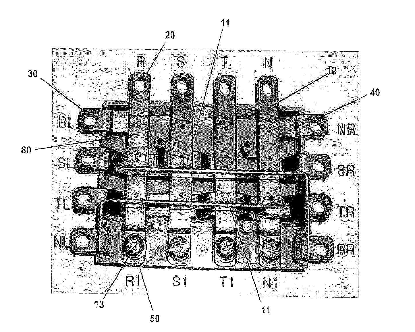
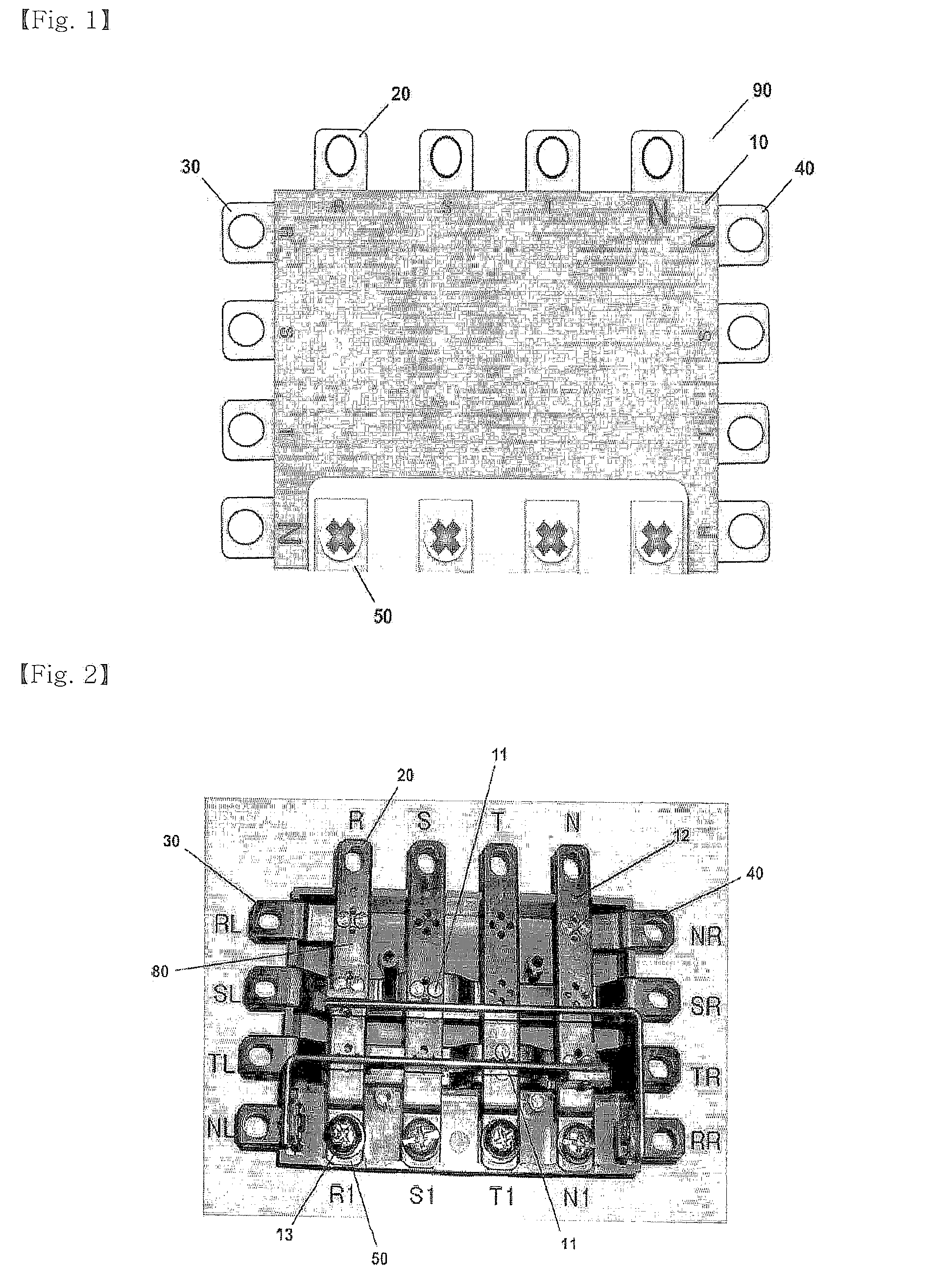
However, the apparatus includes a main breaker terminal and a branch breaker terminal, mostly formed of a
metal bar having high electric
conductivity, such as
copper, whose electric
conductivity and stability are affected by a connection method.
However, such preassembled power distribution apparatuses have problems as below.
However, actually, it causes increase of manufacturing costs to consume much material to increase a thickness of a terminal.
Due to increase of the cost of
copper as
raw material, manufacturing costs of power distribution apparatuses are increased.
However, it is avoided to use a material substituted for the
copper due to a deformation or unfastening of screw coupling caused by heat when using the material substituted for the copper, the material which has workability or mechanical characteristics inferior to those of the copper.
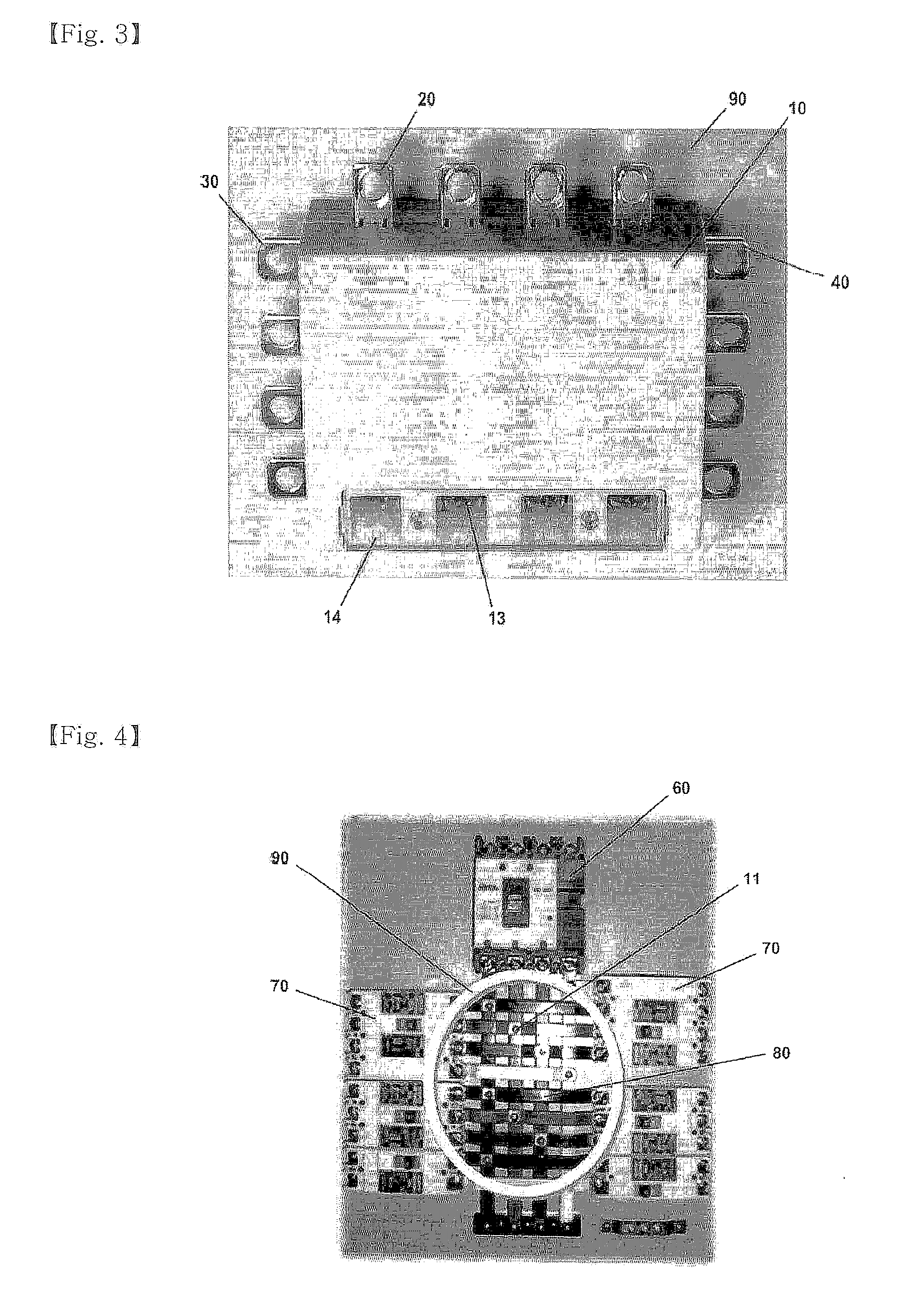
(3) In the case of preassembled power distribution apparatuses, since a main breaker terminal and a branch breaker terminal are installed therein and power is supplied via the terminals, there occurs a lot of heat in a case.
However, since conventional preassembled power distribution apparatuses are perfect closed, which make it difficult to
discharge heat.

