Roadway track with vertical pivot joint

a technology of vertical pivot joint and roadway track, which is applied in the direction of single unit paving, construction, way, etc., can solve the problems of affecting the vehicle's progress, and affecting the smoothness of the roadway

Active Publication Date: 2017-05-18
MUSTHANE
View PDF13 Cites 1 Cited by
  • Summary
  • Abstract
  • Description
  • Claims
  • Application Information

AI Technical Summary

Benefits of technology

[0032]The mounting member thus makes it possible to connect the track portion to the second portion. By way of example, it may be a hinge connection.

Problems solved by technology

However, sometimes that curving causes difficulties since it leads to wrinkles appearing across the mat, forming humps that hinder progress of the vehicle.
The appearance of wrinkles is due to the fact that the mats are made from materials presenting considerable lateral stiffness, in particular because of their width.

Method used


Image

  • Roadway track with vertical pivot joint
  • Roadway track with vertical pivot joint
  • Roadway track with vertical pivot joint

Examples


Embodiment Construction

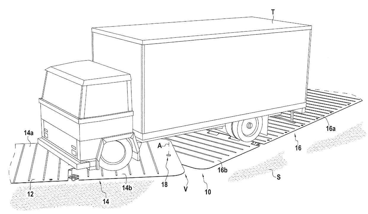
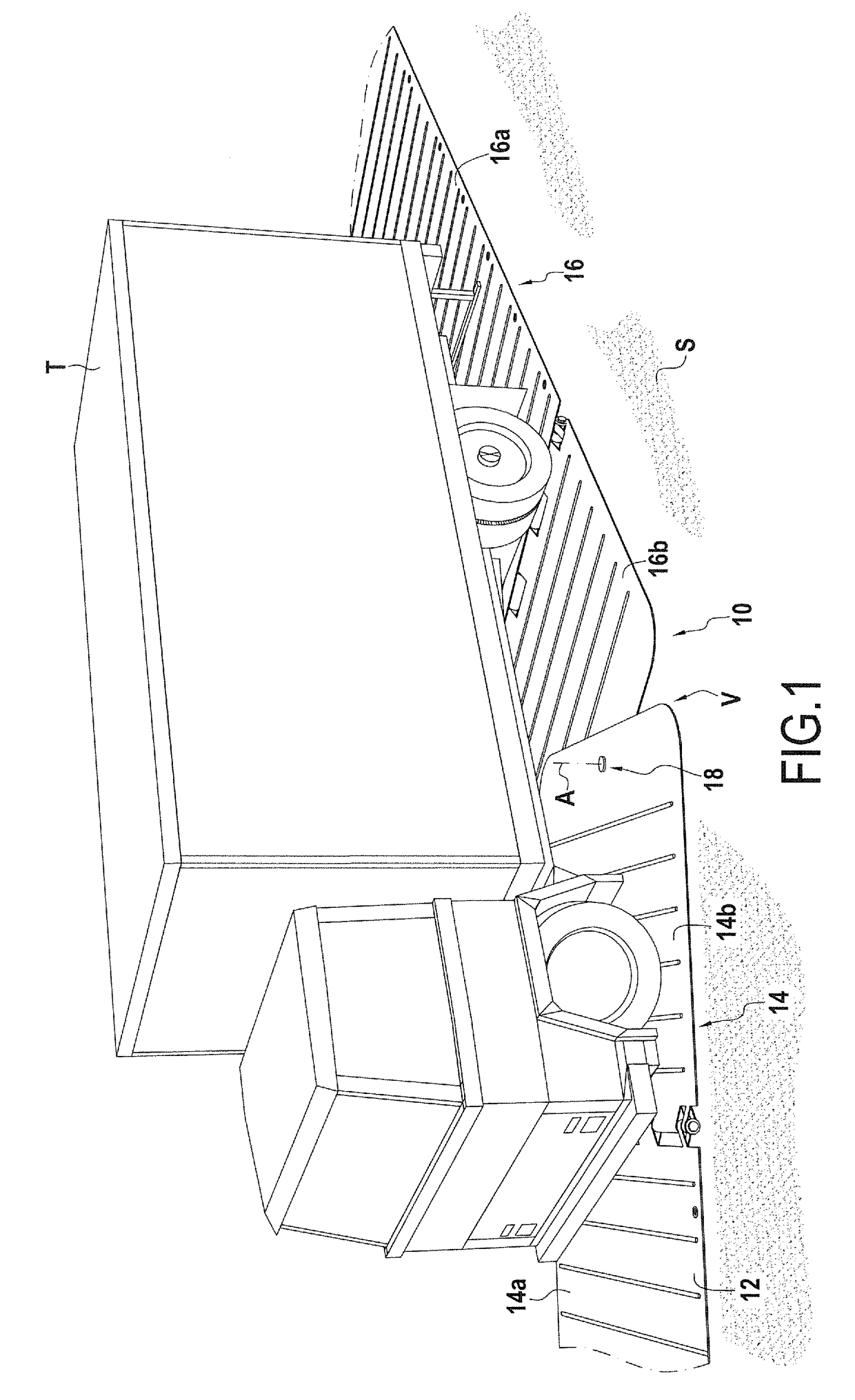
[0042]FIG. 1 shows an embodiment of a roadway track 10 constituting the present disclosure. This roadway track 10 is designed to enable a vehicle T to move on soft ground. In this example, the ground is sandy.

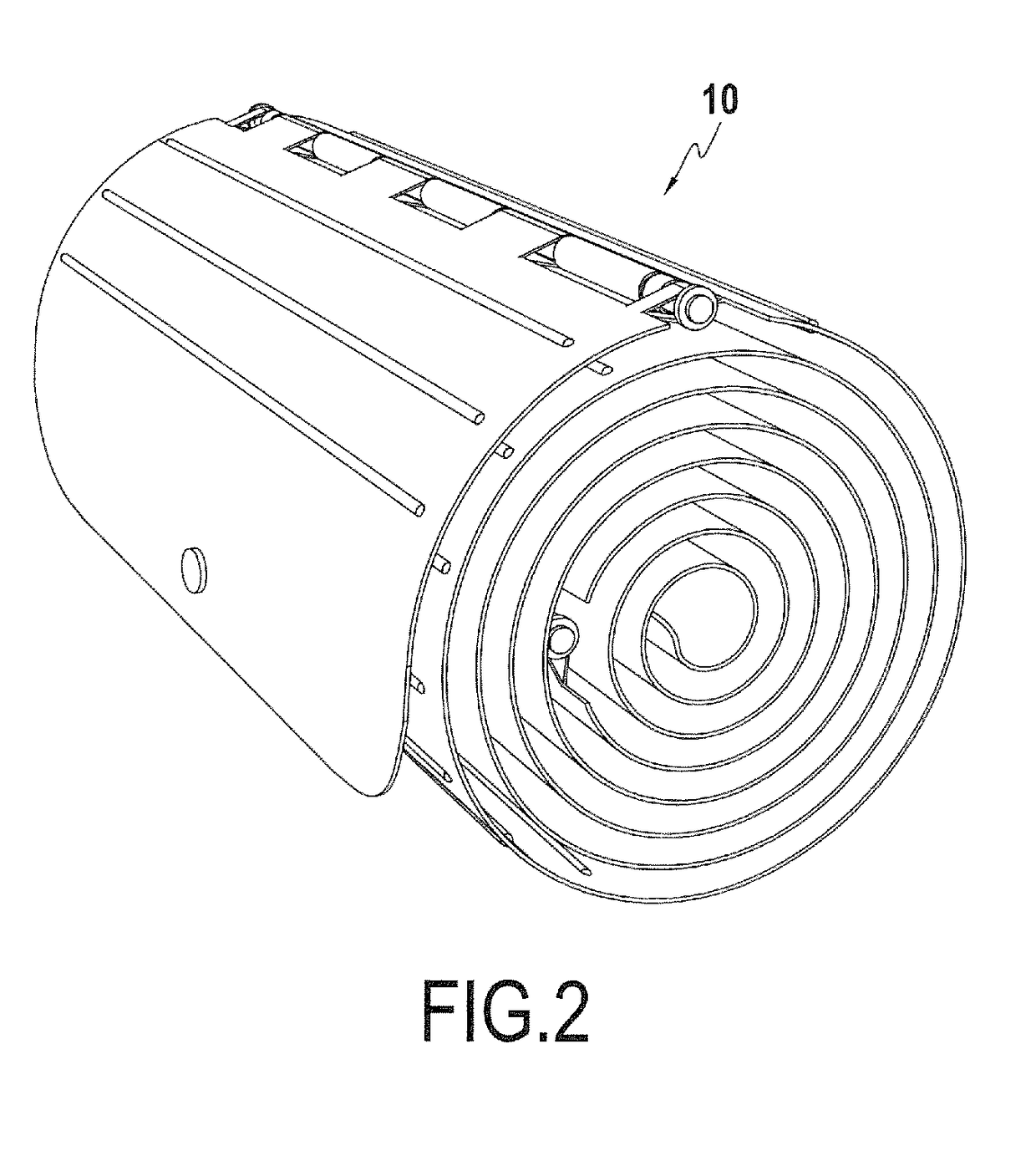
[0043]In FIG. 1, the roadway track 10 is in its deployed position, its roadway face 12 being defined as being the face that is oriented upwards. In FIG. 2, the roadway track 20 is in its rolled-up position.

[0044]As can be seen in FIG. 1, in its deployed position, the roadway track 10 extends substantially parallel to the ground S.

[0045]In accordance with the disclosure, the roadway track 10 comprises at least a first track portion 14 and a second track portion 16, the first and second track portions extending substantially parallel to the ground S when the roadway track 10 is in the deployed position.

[0046]The first and second track portions 14, 16 are connected to each other by a pivot connection 18 having a pivot axis A that extends in a direction substantially perpendicular ...


PUM

PropertyMeasurementUnit
coefficient of frictionaaaaaaaaaa
flexibleaaaaaaaaaa
curvatureaaaaaaaaaa

Abstract

The invention relates to a roadway track (10) for a vehicle (T), said roadway track having a roadway face and being suitable for being rolled up and designed to be placed on a ground and presenting a rolled-up position and a deployed position in which said roadway track extends substantially parallel to the ground.
The roadway track comprises at least a first track portion (14) and a second track portion (16), the first and second track portions being connected to each other by a pivot connection (18) having a pivot axis (A) that extends in a direction that is substantially perpendicular to the roadway face, whereby the first track portion can pivot relative to the second track portion about the pivot axis so as to form a bend (V).

Description

BACKGROUND OF THE DISCLOSURE[0001]The present patent application relates to the field of roadway tracks for vehicles, in particular tracks that are disposed on the ground in temporary manner, in particular so as to facilitate moving the vehicles. By way of example, such a track may be placed on loose ground, e.g. sand, on muddy terrain, or on rough ground, so as to create an access path for vehicles.[0002]Traditionally, such tracks are suitable for being rolled up, and they present both a rolled-up position and a deployed position in which said roadway track extends substantially parallel to the ground. Generally, such tracks are constituted by rectilinear mats placed end-to-end so as to constitute a rectilinear access path.[0003]Such a mat is described in particular in US 2006 / 0222804. When a path defining a curve or a bend is required, the mat must be curved so as to provide the desired curvature. However, sometimes that curving causes difficulties since it leads to wrinkles appea...

Claims


Application Information

Patent Timeline
Patent Type & Authority Applications(United States)
IPC IPC(8): E01C9/08E01C5/00
CPCE01C9/08E01C2201/16E01C9/086E01C5/005
Inventor ROSIER, REZA
Owner MUSTHANE
Why Eureka
Try Eureka