Member joining method

a joining method and member technology, applied in the direction of mechanical devices, transportation and packaging, fastening means, etc., can solve the problem of not considering improving the joining strength between the members, and achieve the effect of improving the joining strength between the two

Active Publication Date: 2019-11-19
NISSAN MOTOR CO LTD
View PDF18 Cites 0 Cited by
  • Summary
  • Abstract
  • Description
  • Claims
  • Application Information

AI Technical Summary

Benefits of technology

[0005]Therefore, an object of the present invention is to improve the joining strength between members.
[0007]According to the present invention, the first member and the second member, whose end portions are joined to each other, are integrated by the first resin member and the second resin member being joined; therefore, the joining strength between the two is improved.

Problems solved by technology

The technique disclosed in Patent Document 1 provides a vibration proofing and soundproofing effect by filling a pillar with a foam, but does not consider improving the joining strength between the members.

Method used


Image

  • Member joining method
  • Member joining method
  • Member joining method

Examples


Embodiment Construction

[0021]Embodiments for implementing the present invention are described in detail below with reference to the drawings.

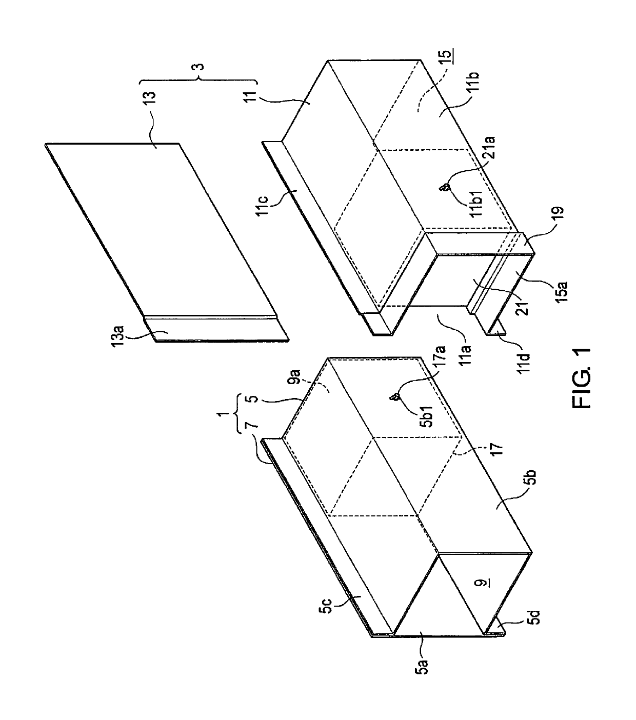
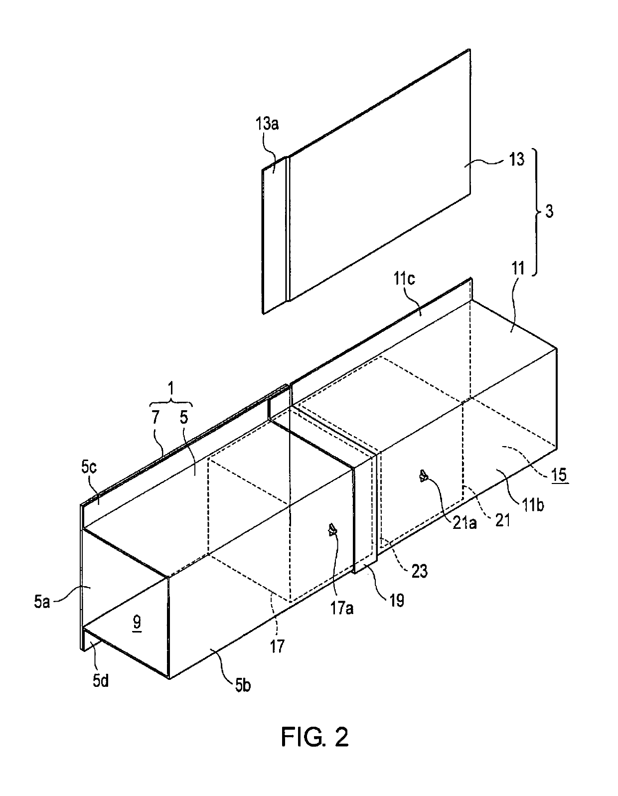
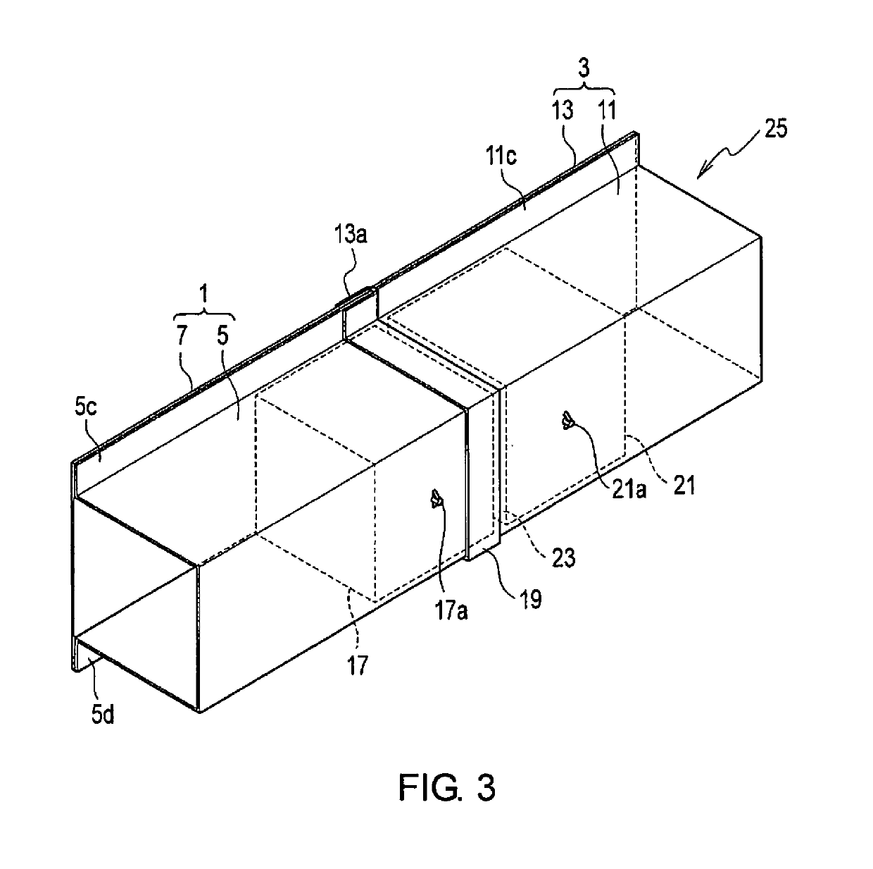
[0022]The first member 1 and the second member 3 shown in FIG. 1 are integrated by the end portions thereof being joined to each other, as illustrated in FIG. 3. The first member 1 is made of metal and is composed of a bent member 5 having a hat-shaped cross section, and a rectangular plate member 7. The bent member 5 has an open portion 5a on one side surface, and forms a rectangular closed cross-sectional space 9 with the plate member 7 by welding and securing the plate member 7 so as to close the open portion 5a.

[0023]In the same manner, the second member 3 is also made of metal and is composed of a bent member 11 having a hat-shaped cross section, and a rectangular plate member 13. The bent member 11 has an open portion 11a on one side surface, and forms a rectangular closed cross-sectional space 15 with the plate member 13 by securing the plate member 13 by wel...


PUM

PropertyMeasurementUnit
joining strengthaaaaaaaaaa
shapeaaaaaaaaaa
timeaaaaaaaaaa

Abstract

A member joining method includes applying a first resin member to a first member and a second resin member to a second member and joining end portions of the first and second members together. The member joining method further includes integrally joining the first resin member of the first member and the second resin member of the second member by heat deformation to mix and cure areas adjacent the end portions at a time of coating.

Description

CROSS-REFERENCE TO RELATED APPLICATIONS[0001]This application is a U.S. national stage application of International Application No. PCT / JP2016 / 063364, filed on Apr. 28, 2016.BACKGROUNDField of the Invention[0002]The present invention relates to a member joining method for joining members to each other.Background Information[0003]Japanese Laid Open Patent Application No. 61-116509 (Patent Document 1) discloses filling a pillar with a foam by injecting a foamed polyurethane into a pillar of an automobile body.SUMMARY[0004]The technique disclosed in Patent Document 1 provides a vibration proofing and soundproofing effect by filling a pillar with a foam, but does not consider improving the joining strength between the members.[0005]Therefore, an object of the present invention is to improve the joining strength between members.[0006]In the present invention, the end portions of a first member and a second member are joined to each other, and a first resin member and a second resin membe...

Claims


Application Information

Patent Timeline
Patent Type & Authority Patents(United States)
IPC IPC(8): B29C44/18B29C44/12B29C65/00F16B11/00B62D27/02B62D29/00B62D25/04
CPCB62D27/026B29C66/5221B62D25/04B29C44/128F16B11/006B62D29/002B29C44/18B62D27/023B29C69/00B29C65/02B62D29/005
Inventor YANO, YUTAKA
Owner NISSAN MOTOR CO LTD
Why Eureka
Try Eureka