Light source module and projector with fan and driver

a technology of light source module and projector, which is applied in the direction of projectors, color television details, instruments, etc., can solve the problems of heat generation of the motor of the fan, inability to dissipate heat, and large heat generated by the high-brightness light source illuminating the phosphor wheel, so as to reduce the overall size and reduce the size of the case

Active Publication Date: 2021-06-29
QISDA CORP
View PDF22 Cites 0 Cited by
  • Summary
  • Abstract
  • Description
  • Claims
  • Application Information

AI Technical Summary

Benefits of technology

[0005]The present invention discloses a light source module with a reduced volume which maintains a good heat dissipation performance.
[0017]As mentioned above, the light source module disclosed in the embodiments of the present invention cools down the temperature of the wavelength transforming unit with the first fan blade and reduces the size of the case. The projector disclosed in the embodiments of the present invention comprises the aforementioned light source module, thus the overall size can be reduced.

Problems solved by technology

However, a light provided by the high brightness light source illuminating the phosphor wheel will generate a large amount of heat.
However, the motor of the fan also creates heat.
And because the optical engine is airtight or almost airtight, the heat cannot be dissipated.
Hence, the fan in the optical engine has to be made out of heat-resistant materials of higher cost.

Method used


Image

  • Light source module and projector with fan and driver
  • Light source module and projector with fan and driver

Examples


first embodiment

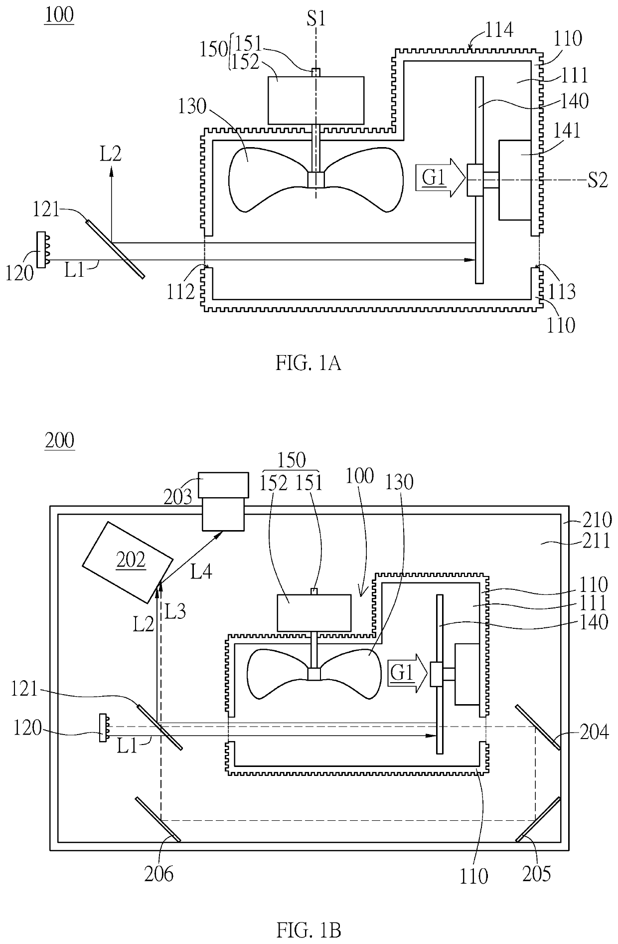
[0028]In the specification, the wavelength transforming unit 140 is, for example, a phosphor wheel. The light source module 100 further includes the driver 141. The wavelength transforming unit 140 is driven by the driver 141 to rotate around the axis S2. The wavelength transforming unit 140 further includes, for example, a passing area and at least one fluorescent powder area. When the wavelength transforming unit 140 rotates around the axis S2, the passing area and the fluorescent powder area will cut into the light path of the excitation light L1. In an embodiment, the wavelength transforming unit can further include quantum dots. However the present invention is not limited to the aforementioned embodiment.

[0029]Furthermore, in the first embodiment, the driver 141 is arranged in the accommodation space 111; however, this invention is not limited thereto. In an embodiment, the driver rotating the wavelength transforming unit can be arranged outside of the case. The driver is exte...

second embodiment

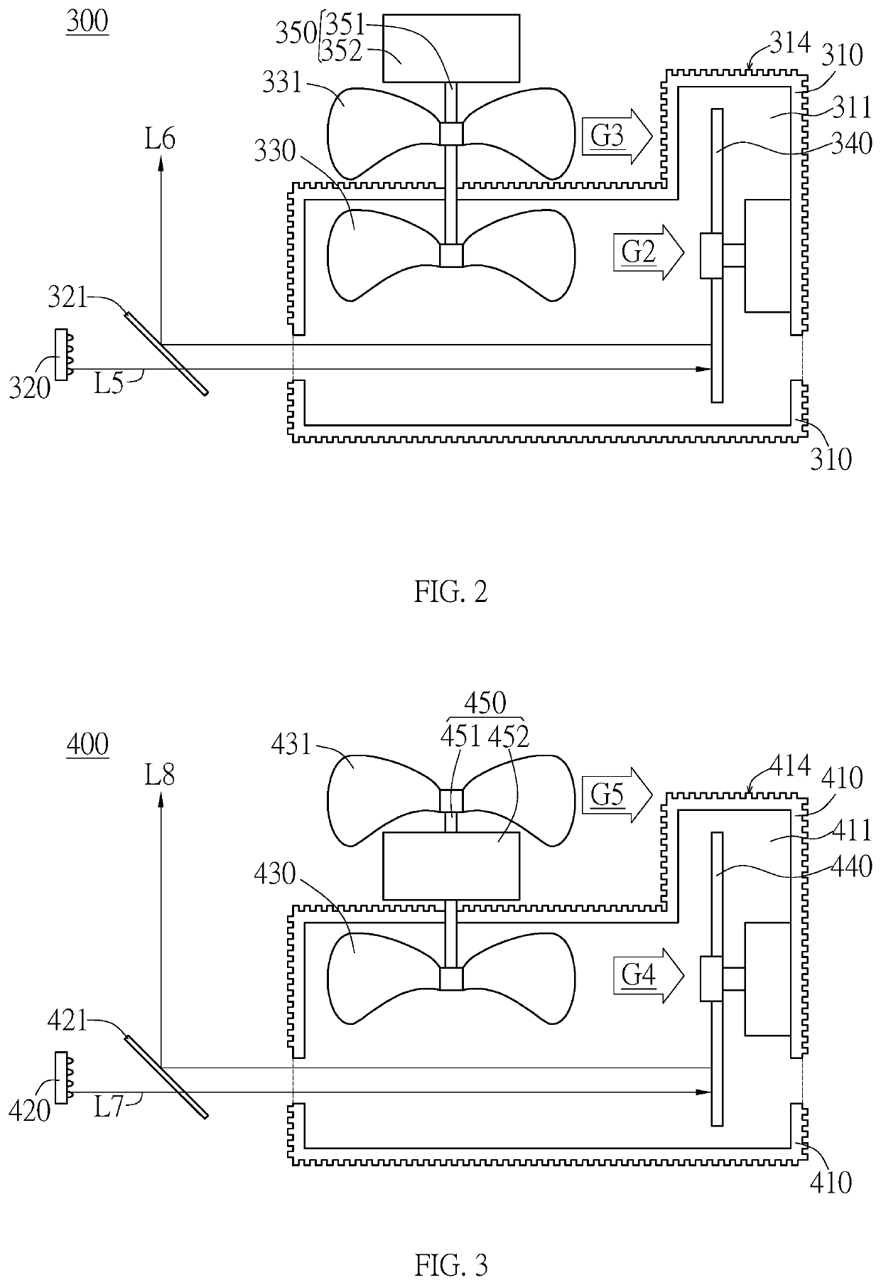
[0040]In other embodiment, the light source module further includes the second fan blade and the third fan blade at the same time. The present invention is not limited by the light source 300 to the second embodiment and the light source 400 to the third source embodiment.

[0041]As mentioned above, the first fan blade can reduce the temperature of the wavelength transforming unit arranged in the case of the presented light source module. At the same time, the first fan blade can be driven by the driving shaft extended to the case. Hence, the size of the case can be reduced by moving the driver outside the case. Because the presented projector comprises the aforementioned light source module, the size of the presented projector can be reduced.


PUM


Abstract

A light source module for providing an illumination light is presented. The light source module comprises a case, a light source, at least one first fan blade, a wavelength transforming unit and a driver. The case has an accommodation space, and the light source provides an excitation light to the accommodation space. The first fan blade and the wavelength transforming unit are disposed in the accommodation space. The wavelength transforming unit receives the excitation light from the light source. The excitation light is transformed into the illumination light through the wavelength transforming unit. The driver includes a driving shaft and a stator for rotating the driving shaft. The stator is located outside the accommodation space. The driving shaft passes through the case and connects to at least one first fan blade. A first air flow is generated by the first fan blade driven by the stator rotating the driving shaft. The first air flow flows inside the case. A projector is also provided.

Description

BACKGROUND OF THE INVENTION1. Field of the Invention[0001]The present invention discloses an optical equipment and an optical device, in particular, the present invention discloses a light source module and a projector.2. Description of the Prior Art[0002]With the progress of optical technologies, solid-state light source having high brightness and high intensity has been applied to projectors to provide a high intensity image. With a laser light source, e.g. laser diode, and a phosphor wheel which is used for transforming wavelength of lights, the projector can project a colorful image to a screen at a distance, and it can even project to a large-sized screen. The aforementioned projector has been used in, for example, performing venues, movie theaters or large-scale conferences.[0003]However, a light provided by the high brightness light source illuminating the phosphor wheel will generate a large amount of heat. To prevent damage to the phosphor wheel, the optical engine accommod...

Claims


Application Information

Patent Timeline
Patent Type & Authority Patents(United States)
IPC IPC(8): G03B21/16G03B21/20H04N9/31G03B21/00
CPCG03B21/16G03B21/204H04N9/3144G03B21/008
Inventor LIN, CHI-CHENGWU, PO-FU
Owner QISDA CORP
Why Eureka
Try Eureka