Industrial ejector having improved suction performance

a technology of industrial ejectors and suction pipes, which is applied in the direction of machines/engines, jet pumps, non-positive displacement pumps, etc., can solve the problems of choked air in the inhaled secondary flow, and achieve the effect of improving suction performan

Active Publication Date: 2021-11-16
JAPAN AEROSPACE EXPLORATION AGENCY
View PDF9 Cites 0 Cited by
  • Summary
  • Abstract
  • Description
  • Claims
  • Application Information

AI Technical Summary

Benefits of technology

[0013]The present invention provides an industrial ejector in which suction performance is improved.
[0015]According to the aspect of the present invention, for example, in a case where the Mach number of the flow velocity of the fluid flowing through the throat is 1, pressure of the fluid drops at the downstream side of the throat in the first channel. Since the opening of the first channel is inclined toward the first side as it goes toward the downstream side, the fluid in which pressure has dropped flows toward the first side as it goes toward the downstream side. The second fluid is efficiently inhaled through the second channel by the fluid in which pressure has dropped. Therefore, the suction performance of the industrial ejector can be improved.
[0017]According to the aspect of the present invention, the fluid in which pressure has dropped at the downstream side of the throat in the first channel flows toward the first side in a more appropriate direction, and thus the suction performance of the industrial ejector can be further improved.
[0019]According to the industrial ejector described above, suction performance can be improved.

Problems solved by technology

However, air in the inhaled secondary flow is choked when the pressure of the primary flow reaches Pss.

Method used


Image

  • Industrial ejector having improved suction performance
  • Industrial ejector having improved suction performance
  • Industrial ejector having improved suction performance

Examples


Embodiment Construction

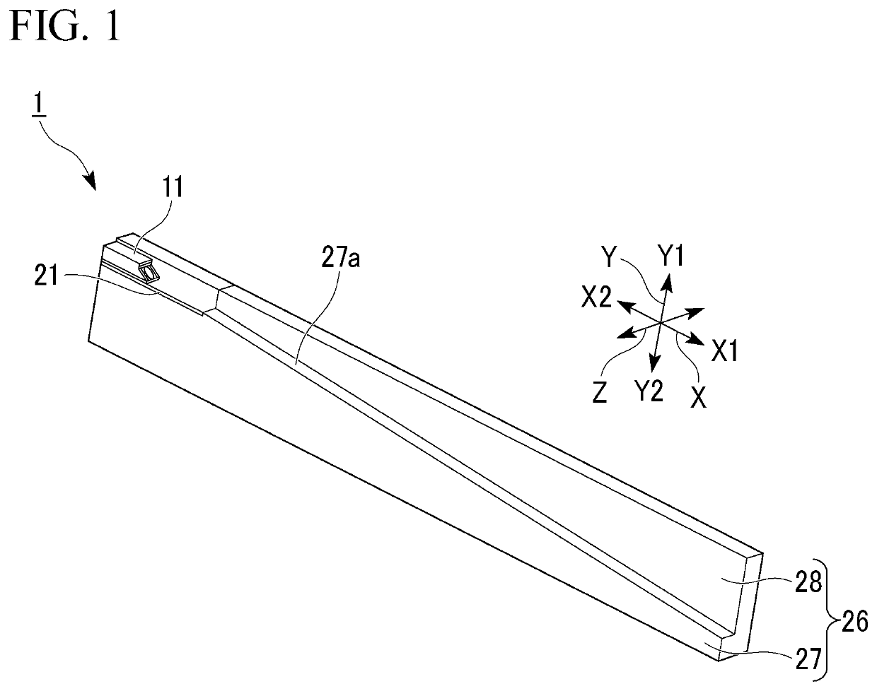
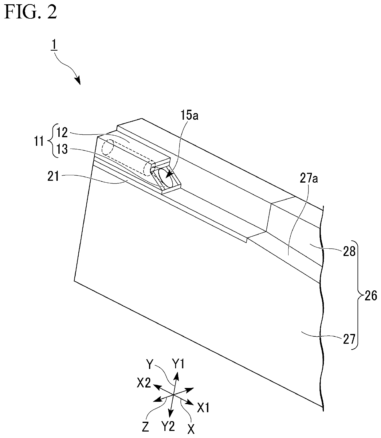
[0027]Hereinafter, an embodiment of an industrial ejector according to the present invention will be described with reference to FIGS. 1 to 6.

[0028]As shown in FIGS. 1 to 3, an industrial ejector 1 of the present embodiment includes a Laval nozzle 11, a chamber (a main body) 21, and a guide member 26. In FIGS. 1 and 2 and FIGS. 5 and 6 to be described below, part of the chamber 21 is not shown.

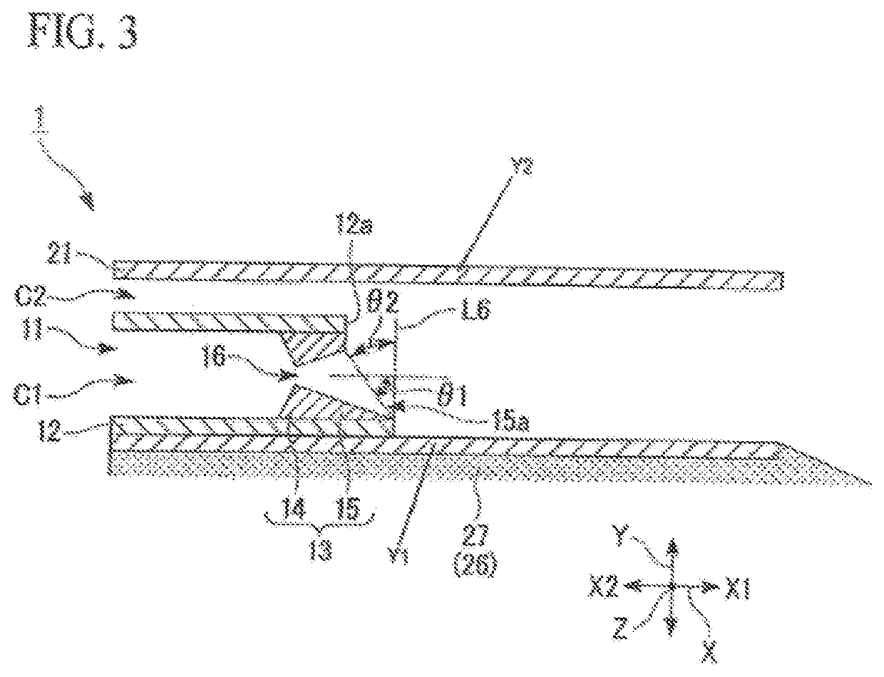
[0029]As shown in FIG. 3, a first channel C1 along which a first fluid flows is formed in the Laval nozzle 11, and a second channel C2 along which second fluid flows is formed in the chamber 21.

[0030]The Laval nozzle 11 includes a tubular part 12 and a protrusion 13. The shape of the tubular part 12 is not limited to configurations of the embodiments. In the present embodiment, the tubular part 12 is formed in an angled tubular shape in which the cross section perpendicular to a longitudinal direction has a rectangular shape. A first direction X in which the first fluid flows in the tubular pa...


PUM


Abstract

An industrial ejector includes: a Laval nozzle in which a first channel which has a throat and along which a fluid flows in a first direction is formed; and a main body which is formed in a tubular shape, in which the Laval nozzle disposed therein is fixed to a part of an inner surface thereof, and in which a second channel is formed between the rest of the inner surface and the Laval nozzle. The second channel is disposed at a first side with respect to the first channel in a second direction perpendicular to the first direction. An opening is obliquely cut and formed in an end of the first channel at a downstream side and inclined toward the first side in the downstream direction and then toward the second channel.

Description

BACKGROUND OF THE INVENTIONField of the Invention[0001]The present invention relates to an industrial ejector.[0002]Priority is claimed on Japanese Patent Application No. 2018-168959, filed Sep. 10, 2018, the content of which is incorporated herein by reference.Description of Related Art[0003]An industrial ejector is a fluid pump that ejects fluid such as water vapor from nozzles and inhales another fluid using negative pressure of the nozzle exit, and is used in an industrial ejector or the like (see, for example, Patent Documents 1 to 3). That is, the industrial ejector that ejects a primary flow at a high speed, and inhales ambient fluid as a secondary flow.[0004]Further, the industrial ejectors are used, for example, in apparatuses for furnace filtration, distillation, infiltration, absorption, drying, mixing, vacuum transportation, vacuum cooling, water cooling, and dewatering in the field of plants.[0005]Patent Document 1: Japanese Unexamined Patent Application, First Publicat...

Claims


Application Information

Patent Timeline
Patent Type & Authority Patents(United States)
IPC IPC(8): F04F5/46F04F5/20
CPCF04F5/465F04F5/20F04F5/466
Inventor HASEGAWA, SUSUMUTANI, KOUICHIRO
Owner JAPAN AEROSPACE EXPLORATION AGENCY
Why Eureka
Try Eureka