Gas supply mask apparatus

a mask and gas supply technology, applied in the field of gas supply mask apparatus, can solve problems such as significant uncomfortable feeling

Active Publication Date: 2015-11-26
ATOM MEDICAL
View PDF12 Cites 3 Cited by
  • Summary
  • Abstract
  • Description
  • Claims
  • Application Information

AI Technical Summary

Benefits of technology

[0006]The present invention can effectively correct the above-described drawbacks of the conventional oxygen mask apparatus 101 and the oxygen mask apparatus 121 of the above-mentioned modification by using a distinct arrangement.

Problems solved by technology

Also, this uncomfortable feeling becomes significant if the volume of air to be breathed in and out increases.

Method used


Image

  • Gas supply mask apparatus
  • Gas supply mask apparatus
  • Gas supply mask apparatus

Examples


Embodiment Construction

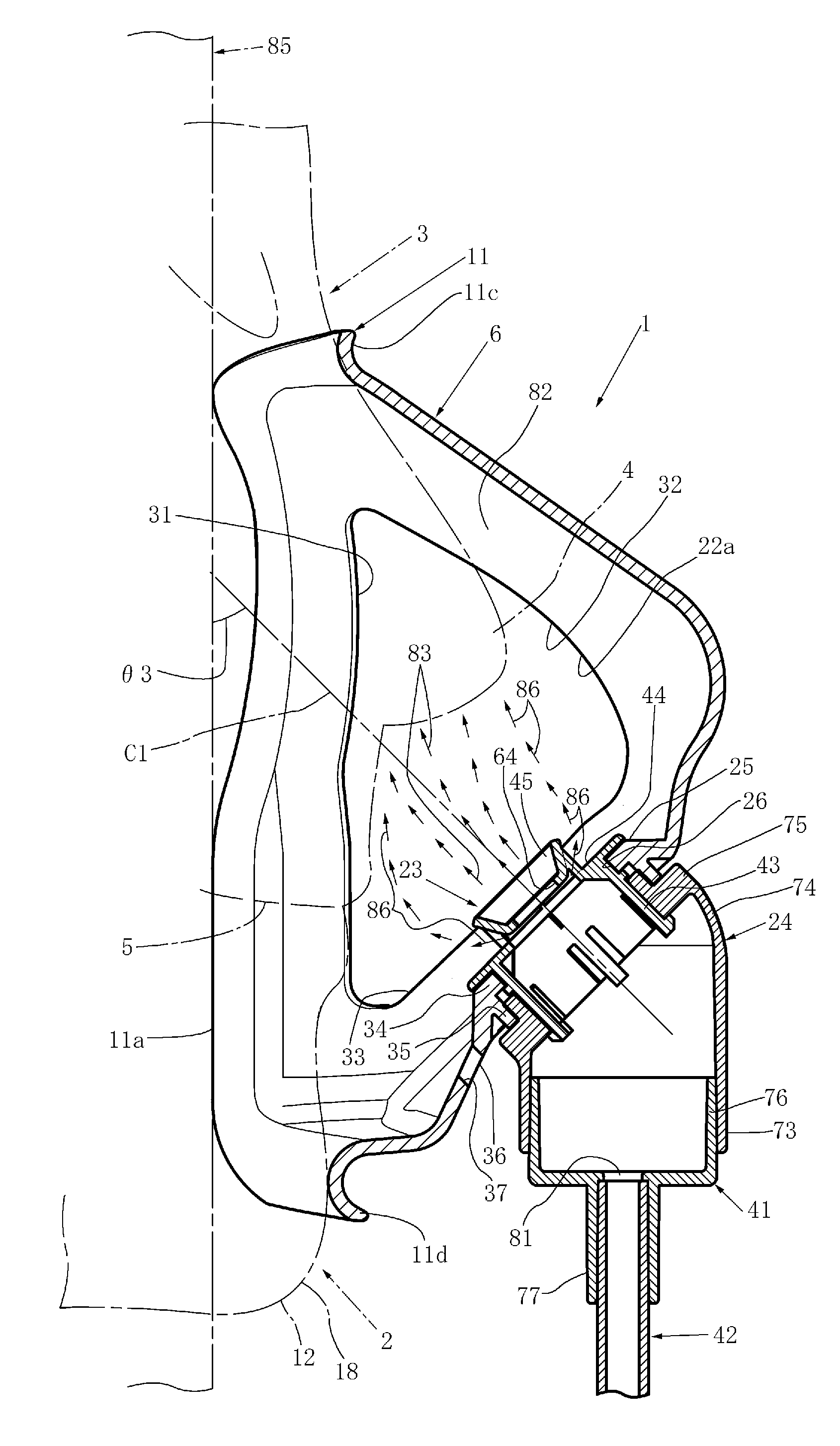
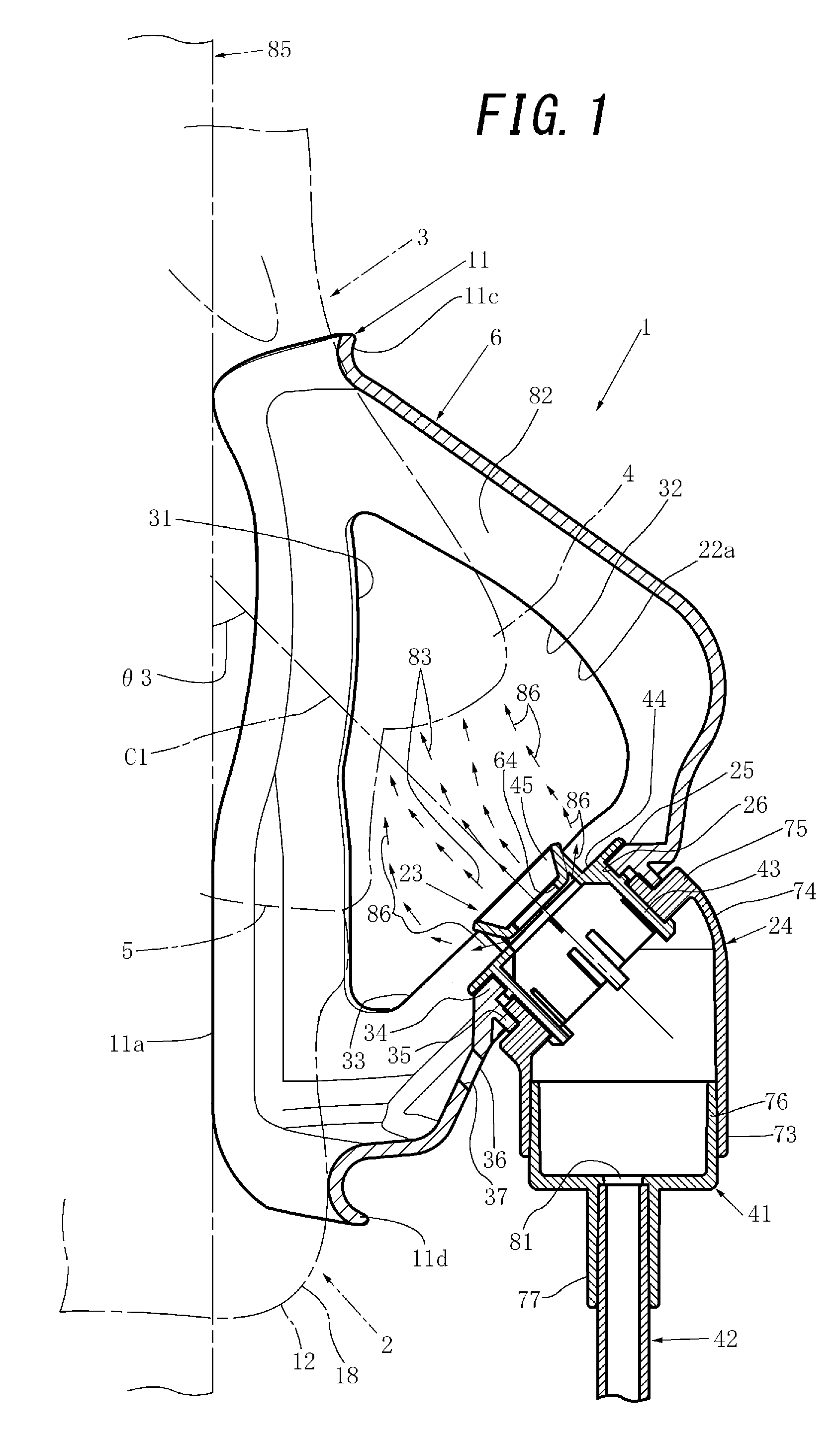
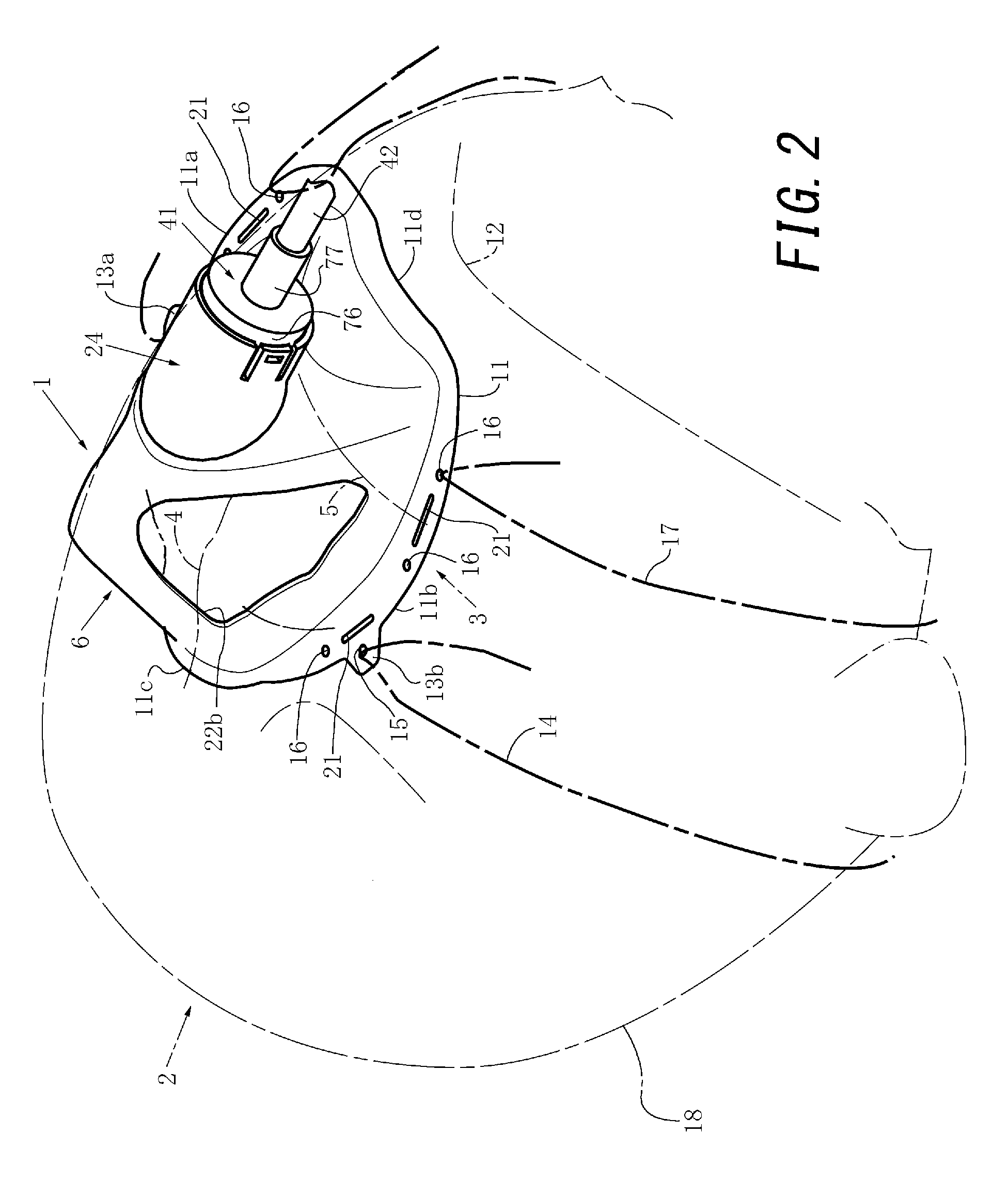
[0030]Next, an oxygen mask apparatus according to an embodiment of the present invention will be explained with reference to FIGS. 1 to 9 by dividing the explanation into “1. Explanation of Oxygen Mask Main Body”, “2. Explanation of First to Fourth Connectors and Gas Supply Tube”, and “3. Explanation of State in Which Gas Is Blown to Mask Main Body”.

[0031]1. Explanation of Oxygen Mask Main Body

[0032]As shown in, e.g., FIGS. 2 and 5, an oxygen mask apparatus 1 as a gas supply mask apparatus includes a mask main body 6 capable of covering a substantially central portion (more specifically, a nose4 and a mouth 5 and their peripheries) of a face 3 of a mask wearer 2 such as a patient. Note that the mask main body 6 can integrally be molded from a substantially transparent (in other words, light-transmitting) soft synthetic resin such as soft vinyl chloride so as to have a substantially bisymmetrical shape and substantially bisymmetrical pattern. At least left and right side portions 11a...


PUM


Abstract

A gas supply mask apparatus allows a mask wearer to inhale a gas such as oxygen gas such that air in a mask main body does not much mix in the gas approaching substantially lower ends and the vicinities of the nostrils of the mask wearer in the mask main body. In this gas supply mask apparatus, a gas introduction opening for introducing a gas such as oxygen gas and water vapor into the mask main body includes a first gas introduction opening capable of introducing the gas in, e.g., a bundle-like state into the mask main body, and a second gas introduction opening capable of introducing the second gas into the mask main body so as to surround, in a substantially ring-like state, the above-mentioned, first gas in a bundle-like state introduced into the mask main body from the first gas introduction opening.

Description

CROSS-REFERENCE TO RELATED APPLICATIONS[0001]This patent application claims priority to Japan Patent Application No. 2014-105147, filed May 21, 2014, and Japan Patent Application No. 2014-112844, filed May 30, 2014, and Japan Patent Application No. 2014-121585, filed Jun. 12, 2014, the disclosures of each of which are herein incorporated by reference in their entirety.TECHNICAL FIELD[0002]The present invention relates to a gas supply mask apparatus such as an oxygen mask apparatus comprising a mask main body wearable on a head of a mask wearer, and a gas introduction opening capable of introducing a gas such as oxygen gas and water vapor to a gas introduction space existing between a face of the mask wearer and the mask main body.BACKGROUND OF THE INVENTION[0003]In FIG. 10, a conventional oxygen mask is shown. A conventional oxygen mask apparatus 101 shown in FIG. 10 differs from an oxygen mask apparatus 1 according to an embodiment of the present invention shown in FIGS. 1 to 8 in ...

Claims


Application Information

Patent Timeline
Patent Type & Authority Applications(United States)
IPC IPC(8): A61M16/06A61M16/08
CPCA61M16/06A61M2202/0208A61M16/0816A61M2202/0007A61M16/0683
Inventor MATSUBARA, KAZUOMATSUBARA, TERUMIKOBAYASHI, KENJIKOBAYASHI, SHINICHI
Owner ATOM MEDICAL
Why Eureka
Try Eureka