
Connector for connection between two fluid-conveying elements
a technology of fluid-conveying elements and connectors, which is applied in the direction of couplings, mechanical devices, etc., can solve the problem of the loss of retainers, etc., and achieve the effect of solving the problem of loss of retainers
- Summary
- Abstract
- Description
- Claims
- Application Information
AI Technical Summary
Benefits of technology
Problems solved by technology
Method used
Image

Examples
Embodiment Construction
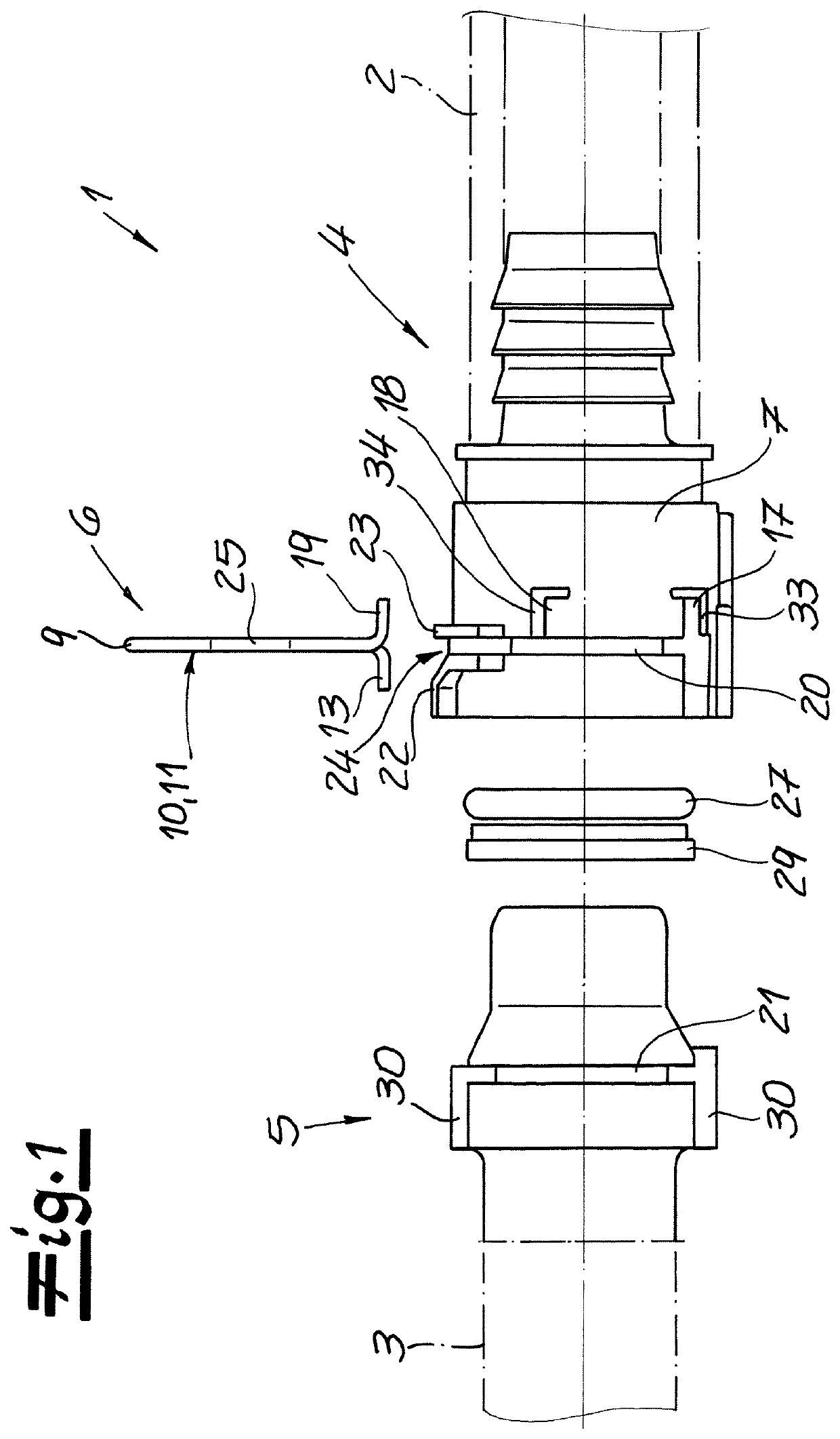
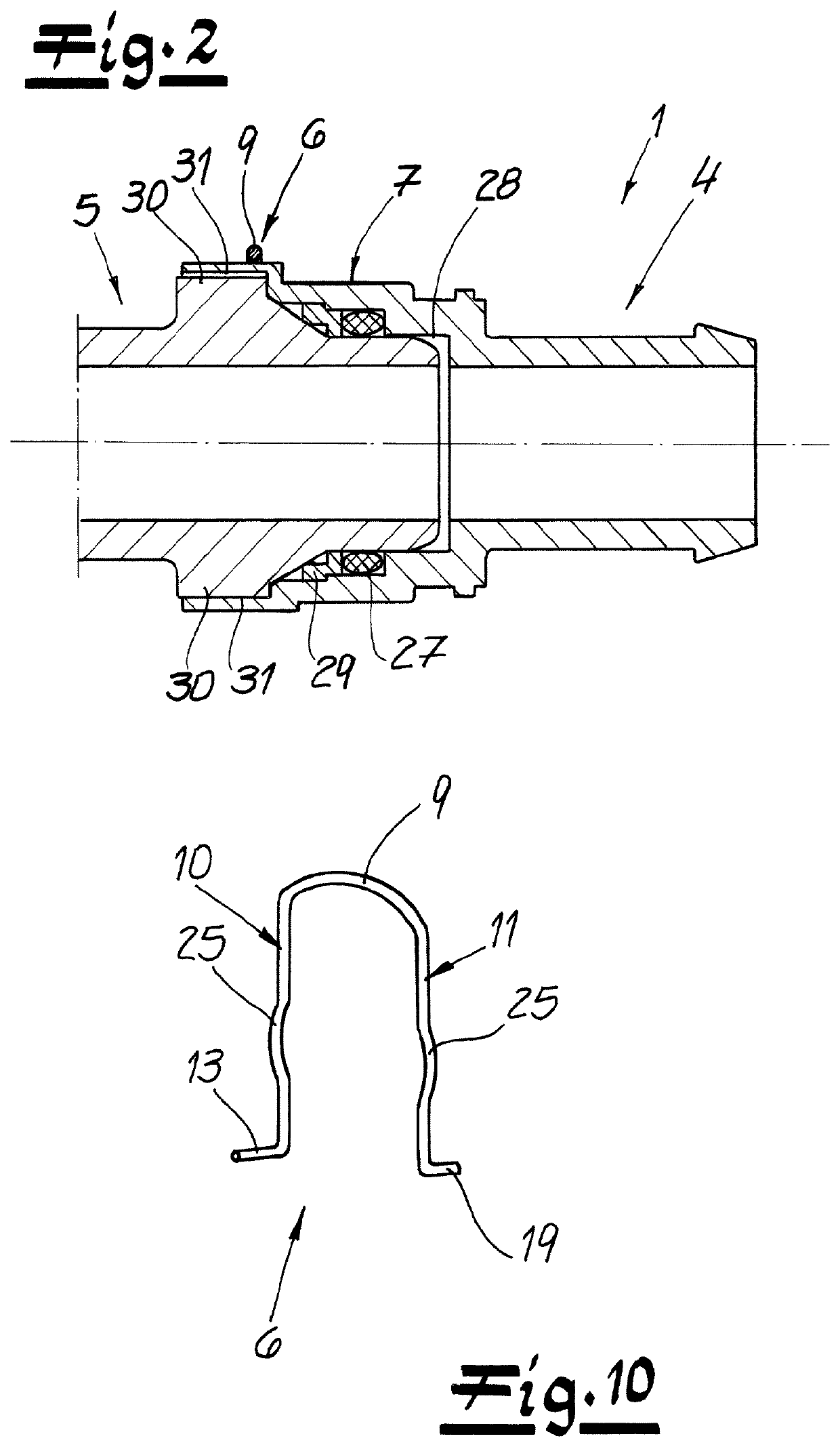
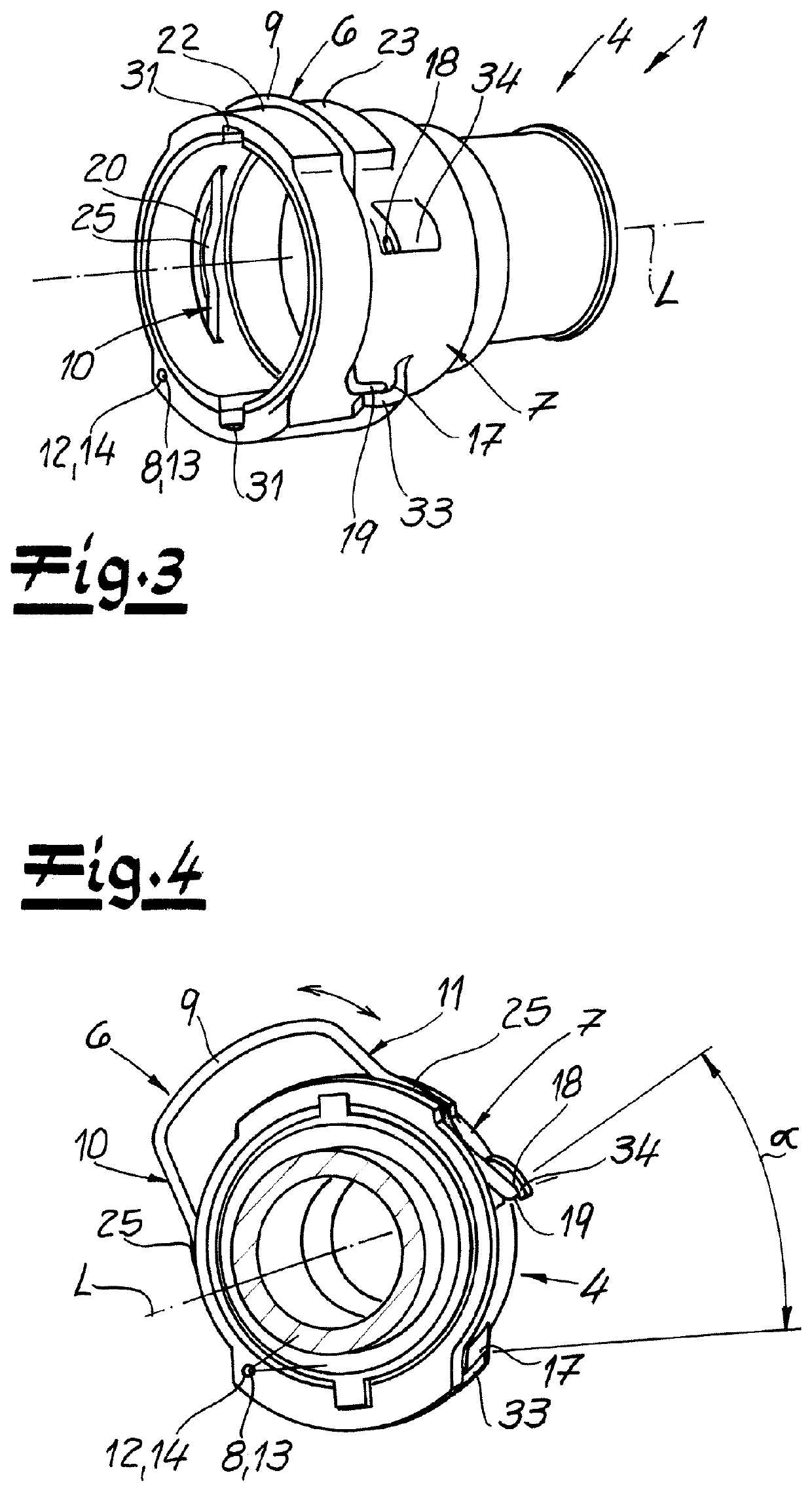
[0034]The figures show a connector 1 according to the invention for connection between two fluid-conveying elements, in particular for connection between two motor vehicle pipes 2, 3. The connector 1 has a female plug-in part 4 and a male plug-in part 5 which is insertable into the female plug-in part 4. At the female plug-in part 4, a retainer 6 is connected and preferably connected in a captive way. With this retainer 6, the male plug-in part 5 in the inserted state (FIG. 2) may be fixed to the female plug-in part 4. The retainer 6 may be transferred from an open position (see, for example, FIG. 4) into a fixing position (see, for example, FIG. 3) and vice versa, and according to the invention it is pivoted about a pivot axis 8 arranged in the region of the outer surface 7 of the female plug-in part 4. The pivoting of the retainer takes place by a pivot angle α, which may be about 45° in the present exemplary embodiment.
[0035]According to a particularly preferred embodiment and in...
PUM
 Abstract
Description
Claims
Application Information