Ureteral access sheath

Inactive Publication Date: 2002-03-28
APPL MEDICAL RESOURCES CORP
View PDF22 Cites 25 Cited by
  • Summary
  • Abstract
  • Description
  • Claims
  • Application Information

AI Technical Summary

Problems solved by technology

This has presented a problem as the sheath has tended to migrate distally and disappear beneath the urethral meatus.
Access devices particularly adapted for other body conduits have had enlargements at the proximal end, but these have not been specifically configured to prevent migration or facilitate the introduction of instrumentation.
Nor has there been any progressive funnel structure which would facilitate the introduction of instrumentation into the working channel of the sheath.

Method used


Image

  • Ureteral access sheath
  • Ureteral access sheath
  • Ureteral access sheath

Examples


Embodiment Construction

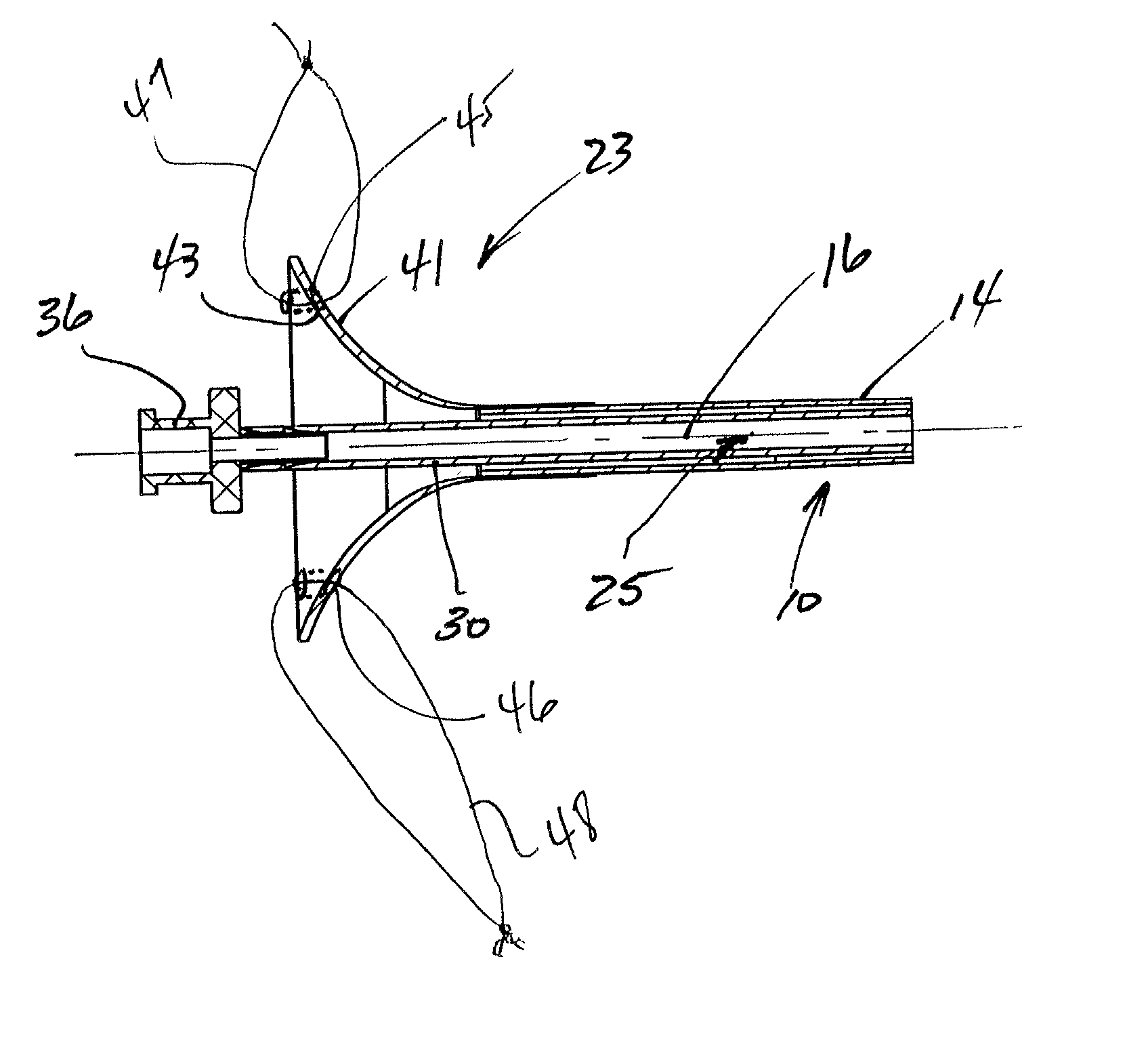
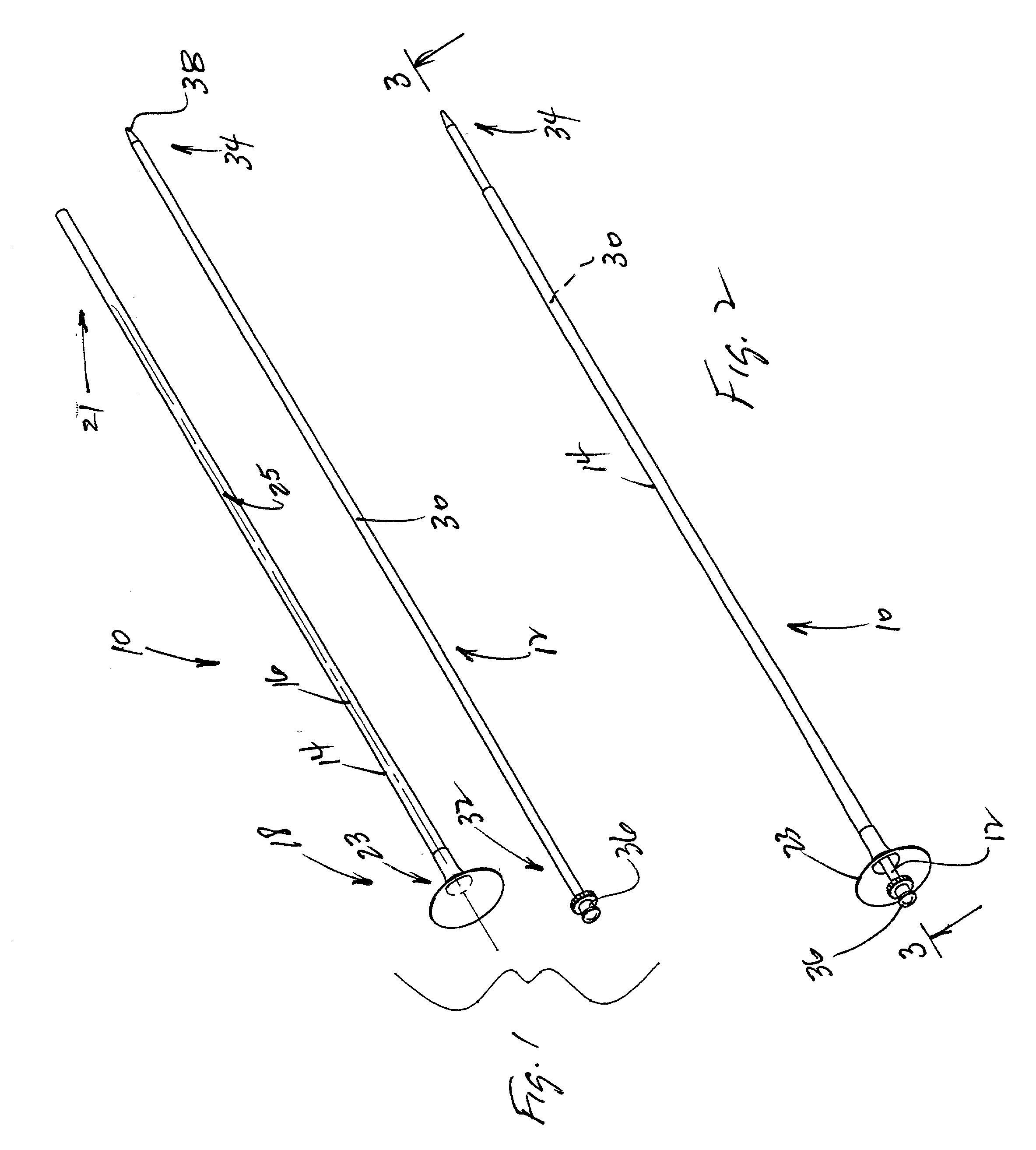
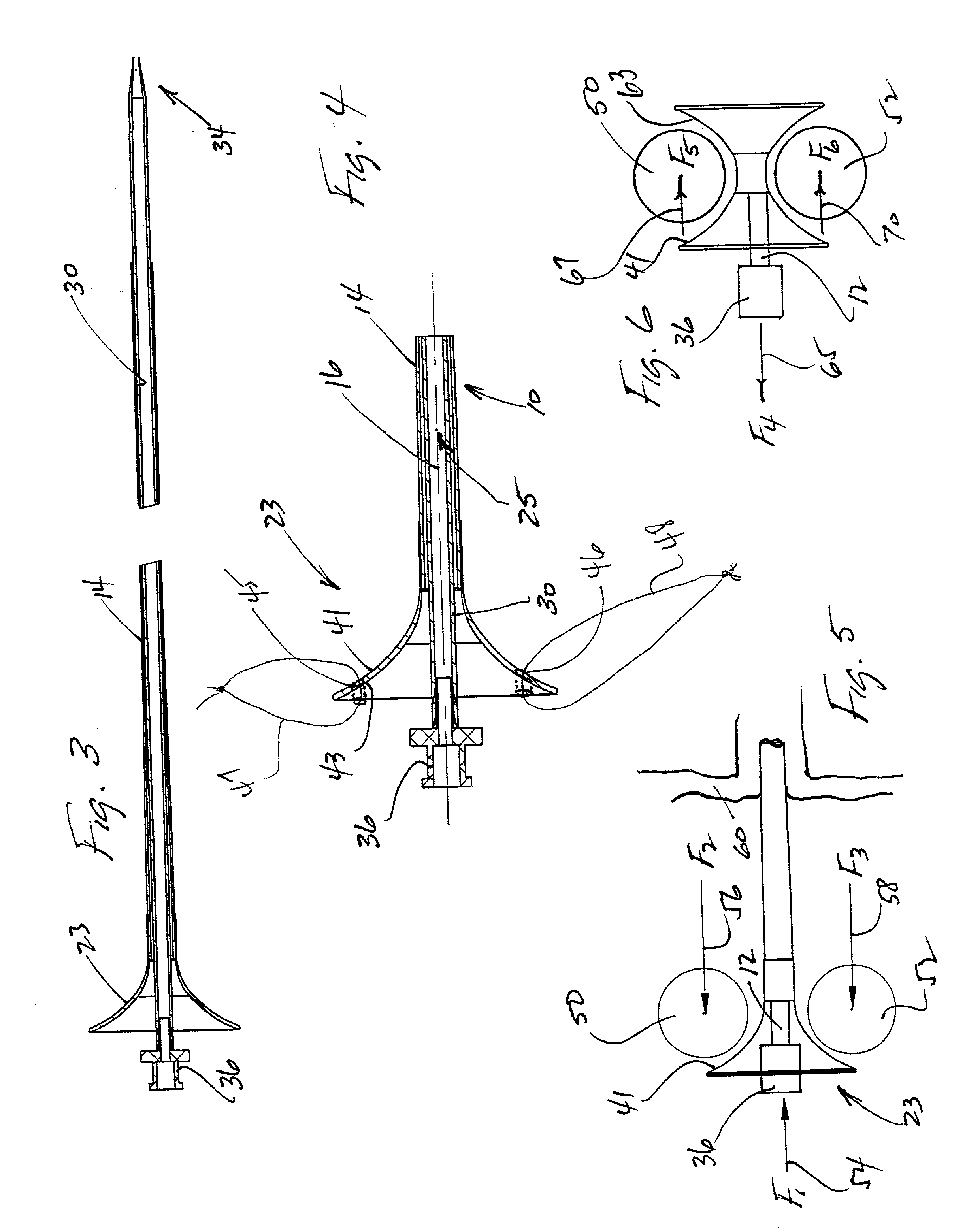
[0025] A ureteral access sheath is illustrated in FIG. 1 and designated generally by the reference numeral 10. In FIG. 1, the sheath 10 is illustrated in combination with a separate, but associated, dilator or obturator 12. The sheath 10 has the general configuration of an elongate tube 14 having an axis 16 which extends between a proximal end 18 and a distal end 21. A handle 23 is disposed at the proximal end 18 of the tube 14 and provides access into a working channel 25 of the tube 14.

[0026] The obturator 12 will typically have the configuration of an elongate rod 30 extending between a proximal end 32 and a distal end 34. A knob 36 is disposed at the proximal end 32 and a tapered tip 38 is formed at the distal end 34. The obturator 12 is adapted to be inserted into the working channel 25 of the sheath 10 with the knob 36 extending proximally of the sheath 10, and the distal end 34 extending distally of the sheath 10. This operative position of the obturator 12 within the sheath ...


PUM


Abstract

A ureteral access sheath adapted for insertion into a urethra includes an elongate tube extending between a proximal end and a distal end. A handle assembly is disposed at the proximal end and includes enlarged portions which inhibit migration of the sheath into the urethra. The enlarged portions are shaped like the bell of a horn with a concave, distally-facing outer surface and a convex, proximally-facing inner surface. The inner surface functions as a funnel while the outer surface is sized and configured to receive adjacent fingers of a user's hand held in its natural position. In an associated method, this shape of the handle assembly facilitates maintaining the sheath in a stationary position during insertion and removal of instrumentation. The handle assembly can be movable on the tube to facilitate variation of the sheath link in situ.

Description

[0001] 1. Field of the Invention[0002] This invention relates generally to guideways for endoluminal access and more specifically to surgical access devices adapted to introduce surgical instrumentation into body conduits.[0003] 2. Discussion of the Prior Art[0004] Surgical access devices of the prior art typically include a sheath having an outside diameter and an inside diameter. An obturator or dilator is inserted into the sheath to facilitate introduction of the sheath into the body conduit. Once the sheath is positioned, the obturator is removed leaving a working channel for surgical instrumentation.[0005] Particularly in the field of urology, the sheath has been provided in the form of an elongate tube having an axis extending between a proximal end and a distal end. The diameter of the tube is generally constant, except for a reduced diameter segment at the distal end. Although the obturator has had an enlarged structure at its proximal end, there has been no such enlargement...

Claims


Application Information

Patent Timeline
Patent Type & Authority Applications(United States)
IPC IPC(8): A61M25/06A61M25/00
CPCA61M25/0014A61M25/0662A61M2025/0681A61M2210/1089A61M25/0017
Inventor DULAK, GARY R.CLAYMAN, RALPH V.
Owner APPL MEDICAL RESOURCES CORP
Why Eureka
Try Eureka