Air-flow control valve device for a helmet

a control valve and airflow technology, which is applied in the direction of headwear caps, protective garments, hats, etc., can solve the problems of helmet without air-flow devices not providing sufficient warm to users, loss of warmth, etc., and achieve the effect of keeping warmth within the helm

Inactive Publication Date: 2005-03-31
LIN CHAN YEN
View PDF12 Cites 19 Cited by
  • Summary
  • Abstract
  • Description
  • Claims
  • Application Information

AI Technical Summary

Benefits of technology

[0006] Accordingly, it is an object of the present invention to provide an air-flow control valve device for a helmet having a helmet body, supporting plate extended to form railing plate and a flow-guiding hood, comprising a valve body being a railing block having two sides mounted with a valve and the top end of the railing blocking being mounted with thread member, and the bottom section being a recessed rail allowing reciprocating of the railing plate of the supporting plate; the flow-guiding hood having a long opening at the top face of the helmet for the passage of the threaded member of the railing block and mounted with a pad, a C-shaped elastic plate to the threaded member and secured by a circular button having a screw hole, and the valve body being pushed by the circular button and positioned and the tension of the C-shaped elastic plate prevented the valve body from moving, and air hole provided to the end portion at the two sides of the helmet being mounted with a valve plate having a push block and a hood shell having a hole which allows the valve plate to move to stop and the passage of air; a warmth-keeping cover being a circular body made of a base cloth and foam by thermal press, the foam being a layer of circular pad body with edge mounted with a plurality of adhesive cloth for adhesion onto the inner frame edge of the helmet and blocking external air to enter the helmet.
[0007] Yet still another object of the present invention is to provide an air-flow control valve device for a helmet, wherein a rain-blocking plate is mounted at the two sides of the supporting plate and at the two sides of the valve to form into a gap allowing air to release, and the valve plate at the bottom end of the two sides of the helmet is pushable to provide an air hole for air stream that flow-in to form a convection current within the helmet, and the air within the helmet and the hot air are discharged via air holes to the air-passage hole and the large opening and via the valve and the gap between the rain-blocking plate to release.
[0008] Still a further object of the present invention is to provide an air-flow control valve device for a helmet, wherein the rain-blocking plates of the valve plate and the supporting plate are closed to prohibit air from releasing, and the valve plate at the end portion of the two sides of the helmet cuts the passage of air via air hole so as to keep the warmth within the helmet, and the hot air within the helmet allows to pass through various air hole to the large opening to the valve plate and the rain-blocking plate, and the air is stopped.

Problems solved by technology

However, the drawback of this conventional helmet is the loss of warmth during the cold season.
The helmet without air-flow device will not fully provide sufficient warm to the user as cold air can enter through the edge of the helmet.

Method used


Image

  • Air-flow control valve device for a helmet
  • Air-flow control valve device for a helmet
  • Air-flow control valve device for a helmet

Examples


Embodiment Construction

[0018] The following descriptions are of exemplary embodiments only, and are not intended to limit the scope, applicability or configuration of the invention in any way. Rather, the following description provides a convenient illustration for implementing exemplary embodiments of the invention. Various changes to the described embodiments may be made in the function and arrangement of the elements described without departing from the scope of the invention as set forth in the appended claims.

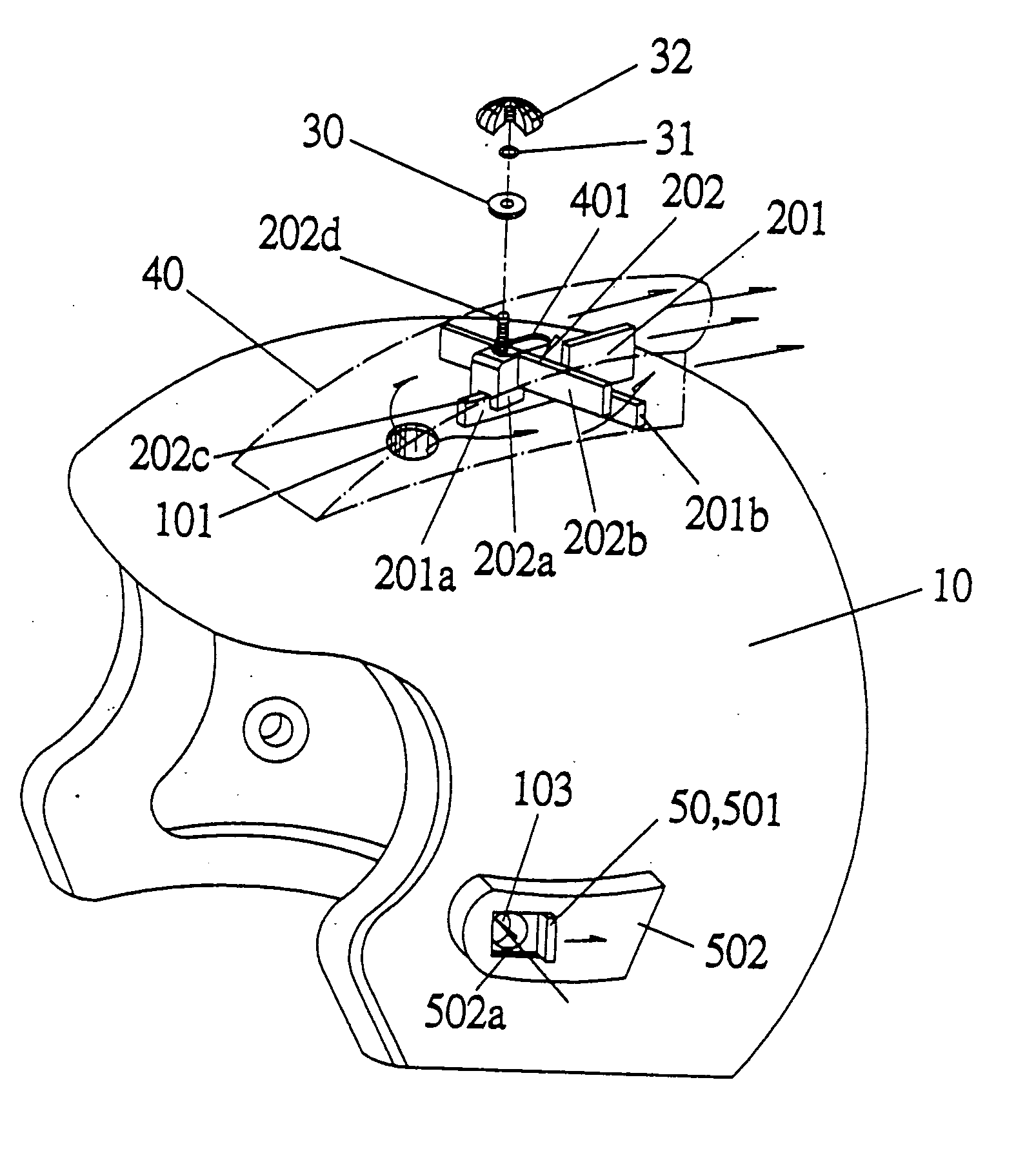
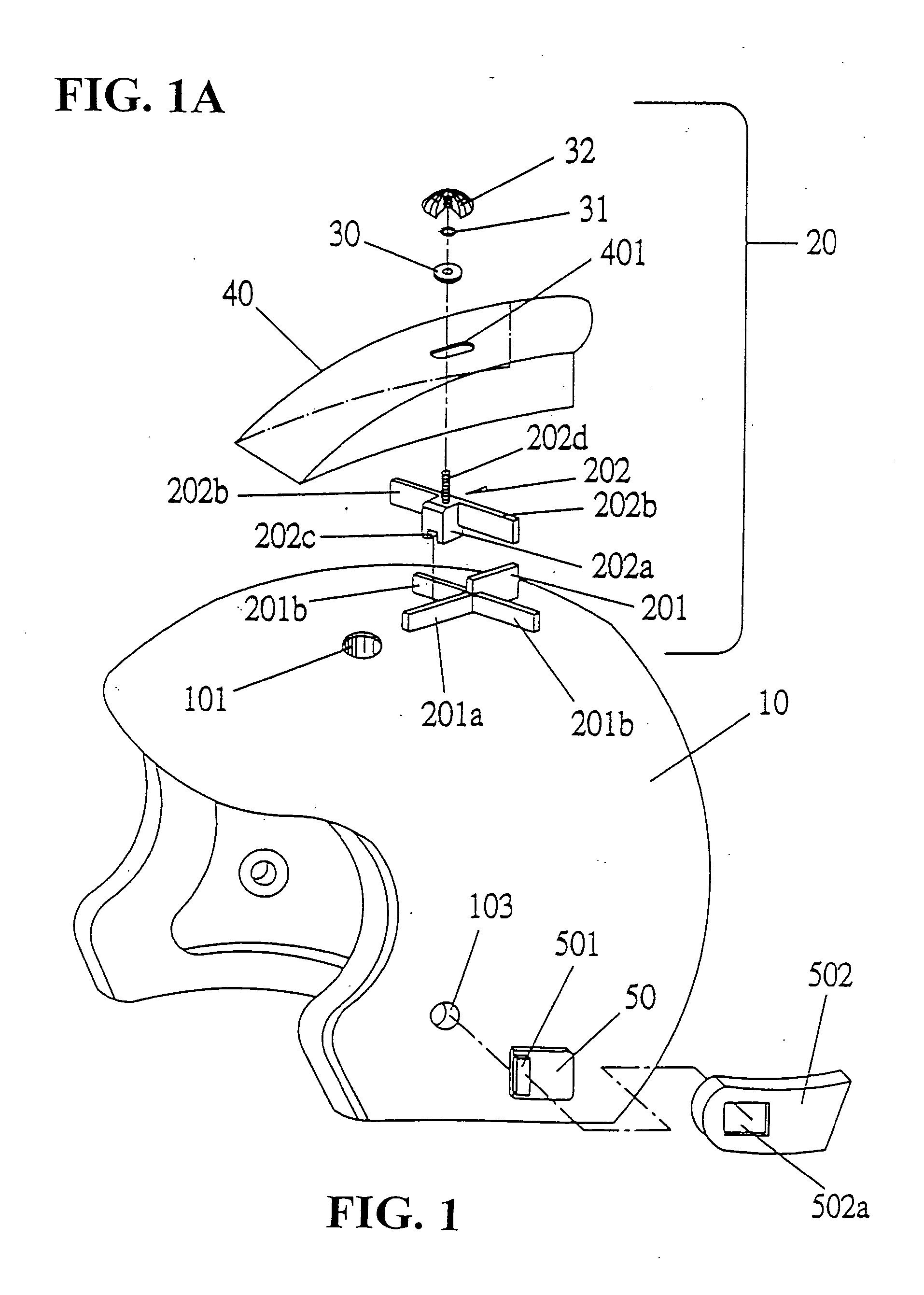
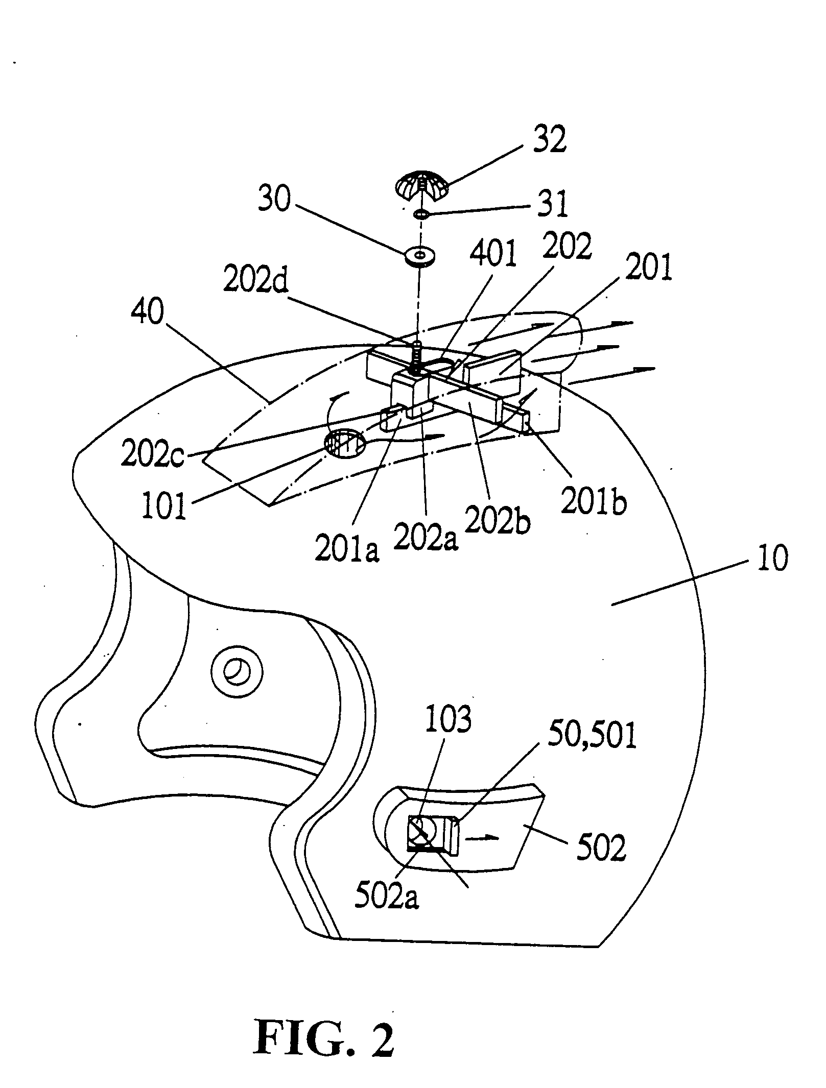
[0019]FIGS. 1 and 1A show an air-flow valve device for a helmet. The larger opening 101 of the top end of the helmet body 10 is provided with an air-flow control valve device 20 at the rear end of the large opening 101. The air-flow control valve body device 20 has a supporting plate extended with a railing plate 21a. The two sides of the supporting plate 201 are provided with a rain-blocking plate 201b, which can prevent rainwater from entering the large opening 101. The supporting plate 201 i...


PUM


Abstract

An air-flow control valve device for a helmet is disclosed. The valve device provides the effect of a warm during the winter and cold effect during the summer. The device is adjustable in accordance with the temperature change so as to provide air-flow and maintain warm. During the summer, the moveable valve gate is pushed forward, and the air within the helmet flows out of the helmet via the gap between the valve gate and the rain-blocking plate. During the winter, the valve gate is pushed backward to seal with the rain-blocking plate to effect the blocking of the heat to release from the helmet. Further, a warmth-keeping member is provided at the frame edge of the helmet to prohibit cold air to enter so as to fully prohibit cold air to enter the head portion and to maintain the warm air from releasing.

Description

BACKGROUND OF THE INVENTION [0001] (a) Technical Field of the Invention [0002] The present invention relates to an air-flow control-valve device for a helmet, and in particular, an air-flow control valve device to provide warmth during the winter and cool during the summer. The device allows the adjustment of the valve gate (forward or backward) so as to achieve air-flow or warm-maintaining effect, which is suitable to various changes of temperature. [0003] (b) Description of the Prior Art [0004] Helmet is a device used to protect the driver while riding a motorcycle. It is known conventionally that there is no air-flow within the helmet and under the hot weather of the summer, the head of the wearer has to withstand the high temperature of the hot air. [0005] In order to overcome the drawback of the helmet of the hot air within the helmet, a plurality of helmet with air-flow device have been exploited to fulfil the demand of the user. The applicant of the present application has al...

Claims


Application Information

Patent Timeline
Patent Type & Authority Applications(United States)
IPC IPC(8): A42B3/28
CPCA42B3/283
Inventor MA, CHANG-CHING
Owner LIN CHAN YEN
Why Eureka
Try Eureka