Fluid pump, cooling system and electrical appliance

a technology of fluid pump and cooling system, applied in the direction of pump, positive displacement liquid engine, machine/engine, etc., can solve the problems of low cooling capacity, increase in the number of parts and over-all dimensions of the system, and in the number of connecting points

Inactive Publication Date: 2005-11-10
KK TOSHIBA
View PDF6 Cites 12 Cited by
  • Summary
  • Abstract
  • Description
  • Claims
  • Application Information

AI Technical Summary

Benefits of technology

[0009] Since the fluid pump thus constructed includes a reserve tank inside the case, the fluid pump can

Problems solved by technology

A purpose of employing the reserve tank is to prevent degradation of the cooling performance, since a decrease in the amount of the liquid refrigerant by evaporation results in a lower cooling capacity.
In such a conventional cooling sys

Method used


Image

  • Fluid pump, cooling system and electrical appliance
  • Fluid pump, cooling system and electrical appliance
  • Fluid pump, cooling system and electrical appliance

Examples


first embodiment

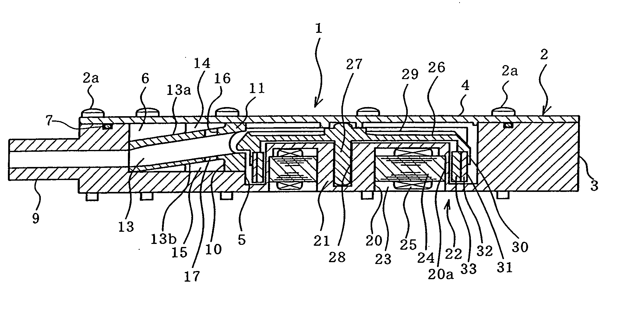
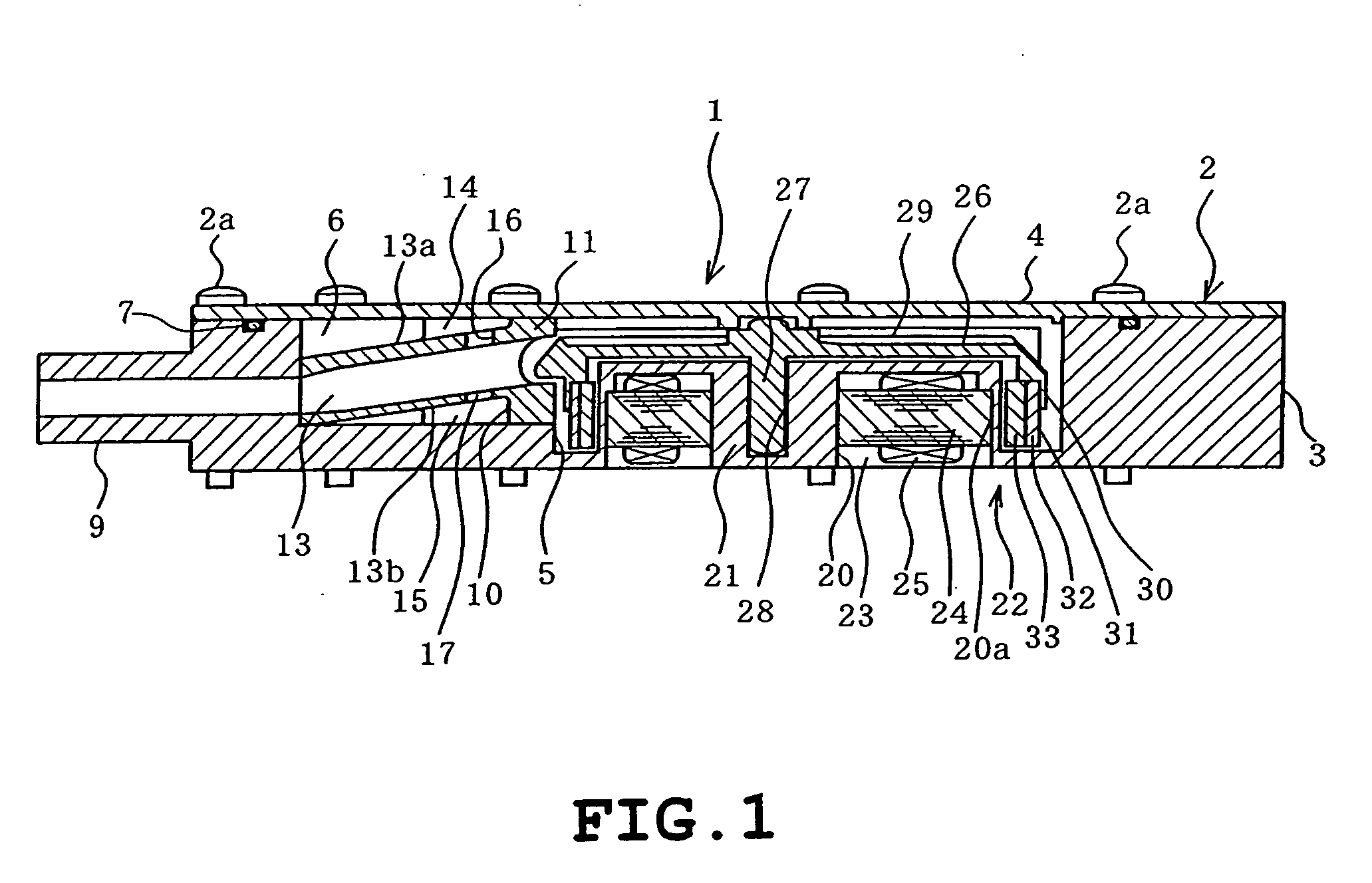
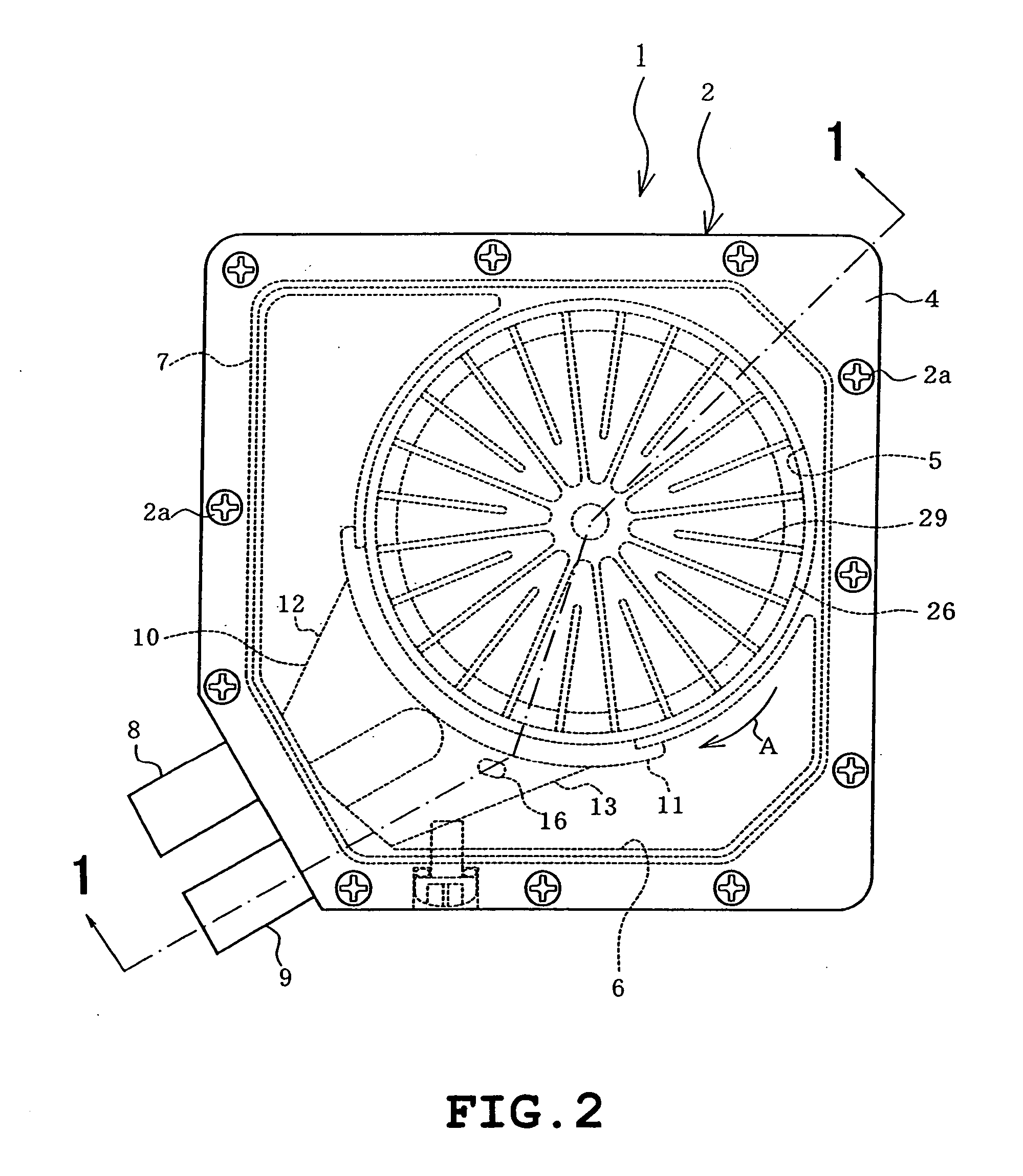
[0031] Referring to FIG. 1 through FIG. 8, the present invention will be described hereunder. FIG. 2 is a plan view showing a fluid pump 1 according to the present invention, while FIG. 1 is a cross sectional view taken along the line 1-1 of FIG. 2, FIG. 3 is an exploded perspective view and FIG. 4 is an exploded perspective view viewed from an opposite direction from FIG. 3, respectively showing the same fluid pump.

[0032] As shown in FIGS. 1 to 4, a case 2 of the fluid pump 1 is of a generally rectangular shape, and includes a case body 3 and a cover 4 attached thereto with a plurality of screws 2a. The case body 3 includes a circular recessed portion with an opening on the side of the cover 4 to concurrently constitute a pump chamber 5, and another similar recess with an opening on the side of the cover 4 that constitutes a reserve tank 6. The opening of the pump chamber 5 and the reserve tank 6 are closed by the cover 4. Between the case body 3 and the cover 4, a sealing member 7...

third embodiment

[0056] In the cooling system 50 also, the fluid pump 1 includes therein the reserve tank 6, which eliminates the need to additionally install a reserve tank. This allows avoiding an increase in the number of parts and keeping the cooling system 50 from becoming oversized, and further decreasing the number of connection points.

[0057] Now FIGS. 11 through 15 show a cooling system according to a fourth embodiment of the present invention, which is different from the first embodiment in the following aspect.

[0058] A fluid pump 60 is provided with a different number of liquid inlets at different positions from the fluid pump 1 of the first embodiment. Referring to FIG. 12, the case body 3 of the case 2 is provided with a first liquid inlet 61 communicating with the reserve tank 6 and a second liquid inlet 62 communicating with the pump chamber 5, which are located on a side wall on the upper face of the case body 3.

[0059] The first liquid inlet 61 is provided so as to communicate in a...

fourth embodiment

[0065] The arrangement as the fourth embodiment provides the following advantageous effects in particular. The case 2 of the fluid pump 60 is provided with the first liquid inlet 61 communicating with the inside of the reserve tank 6 and the second liquid inlet 62 communicating with the inside of the pump chamber 5. Accordingly, when introducing a liquid through the first liquid inlet 61, air remaining in the pump chamber 5 and in the fluid path communicating therewith can be efficiently discharged outward through the second liquid inlet 62 communicating with the pump chamber 5, and air present in the reserve tank 6 can be easily discharged outward through the first liquid inlet 61.

[0066] If, for example, only the first liquid inlet 61 were provided, without the second liquid inlet 62, the air remaining in the pump chamber 5 and in the fluid path communicating therewith would not be discharged until it is finally discharged through the first liquid inlet 61 after having been led int...


PUM


Abstract

A fluid pump for circulating the cooling liquid to cool the heat-generating part is disclosed. The fluid pump includes a case including a pump chamber for storing a liquid, a suction port and a discharge port provided on the case so as to communicate with the pump chamber, an impeller having pump vanes and rotatably placed in the pump chamber, which suctions a liquid into the pump chamber via the suction port and discharges the liquid out of the pump chamber via the discharge port by rotation, a motor for driving the impeller, installed in the case and having a stator and a rotor to which the impeller is integrally attached for rotating together, a reserve tank for storing spare liquid located and formed in the case but outside the pump chamber, a fluid path forming member arranged inside the reserve tank, including a discharge path communicating between the discharge port and the pump chamber, and a communication hole formed in the fluid path forming member so as to communicate between the discharge path and inside of the reserve tank.

Description

BACKGROUND OF THE INVENTION [0001] 1. Field of the Invention [0002] The present invention relates to a fluid pump suitable for a cooling system that cools heat generating parts. [0003] 2. Description of the Related Art [0004] Conventionally many existing fluid pumps for handling a liquid are provided with a motor having a rotor to which an impeller is integrally fixed for rotation together with the rotor, so that the pump vanes of the impeller serve to suction the liquid into a pump chamber via a suction port, and to discharge the liquid out of the pump chamber via a discharge port. [0005] Such pumps can be incorporated in a cooling system that cools heat-generating parts, including a heat-receiving section that absorbs the heat of the heat-generating parts via a liquid refrigerant and a heat-dissipating section that dissipates the heat transferred to the liquid refrigerant, as a means of circulating the liquid refrigerant through the heat-receiving section and the heat-dissipating ...

Claims


Application Information

Patent Timeline
IPC IPC(8): F04B17/00F04B35/04F04D5/00F04D13/06H05K7/20
CPCF04D13/0673
Inventor ITO, KENICHISEKO, KATSUYATOMIOKA, KENTAROTAKAMATSU, TOMONAONAGASHIMA, FUMIHIDEKOJIMA, TAKAHIRO
Owner KK TOSHIBA
Why Eureka
Try Eureka