Driving device of light source for display device

a technology of a display device and a driving device, which is applied in the direction of electric variable regulation, process and machine control, instruments, etc., can solve the problems of deterioration of image quality, volume and manufacturing cost of the backlight assembly, and lamp luminance imbalance,

Inactive Publication Date: 2005-12-08
SAMSUNG DISPLAY CO LTD
View PDF16 Cites 20 Cited by
  • Summary
  • Abstract
  • Description
  • Claims
  • Application Information

AI Technical Summary

Benefits of technology

[0019] The lamp state sensing unit may include: a reference voltage setting unit connected to the lamps and defining the reference voltage of which the magnitude is varied depending on an average voltage of the AC voltage applied to the lamps; and a plurality of lamp state sensing circuit connected to the respective lamp, comparing the sensed driving voltages of the lamps, of which the magnitude is varied depending on the driving voltages applied to the respective lamps, to the reference voltage, and outputting a plurality of state signals having an information informing the over-current state when the sensed driving voltage is smaller than the reference voltage, respectively.

Problems solved by technology

The leakage current difference brings an imbalance in luminance of lamps and deterioration of the image quality.
Since a separate transformer is required for controlling each lamp, the volume and the manufacturing cost of the backlight assembly become enlarged.

Method used


Image

  • Driving device of light source for display device
  • Driving device of light source for display device
  • Driving device of light source for display device

Examples


Embodiment Construction

[0042] The present invention will now be described more fully hereinafter with reference to the accompanying drawings, in which preferred embodiments of the inventions invention are shown.

[0043] In the drawings, the thickness of layers and regions are exaggerated for clarity. Like numerals refer to like elements throughout. It will be understood that when an element such as a layer, film, region, substrate or panel is referred to as being “on” another element, it can be directly on the other element or intervening elements may also be present. In contrast, when an element is referred to as being “directly on” another element, there are no intervening elements present.

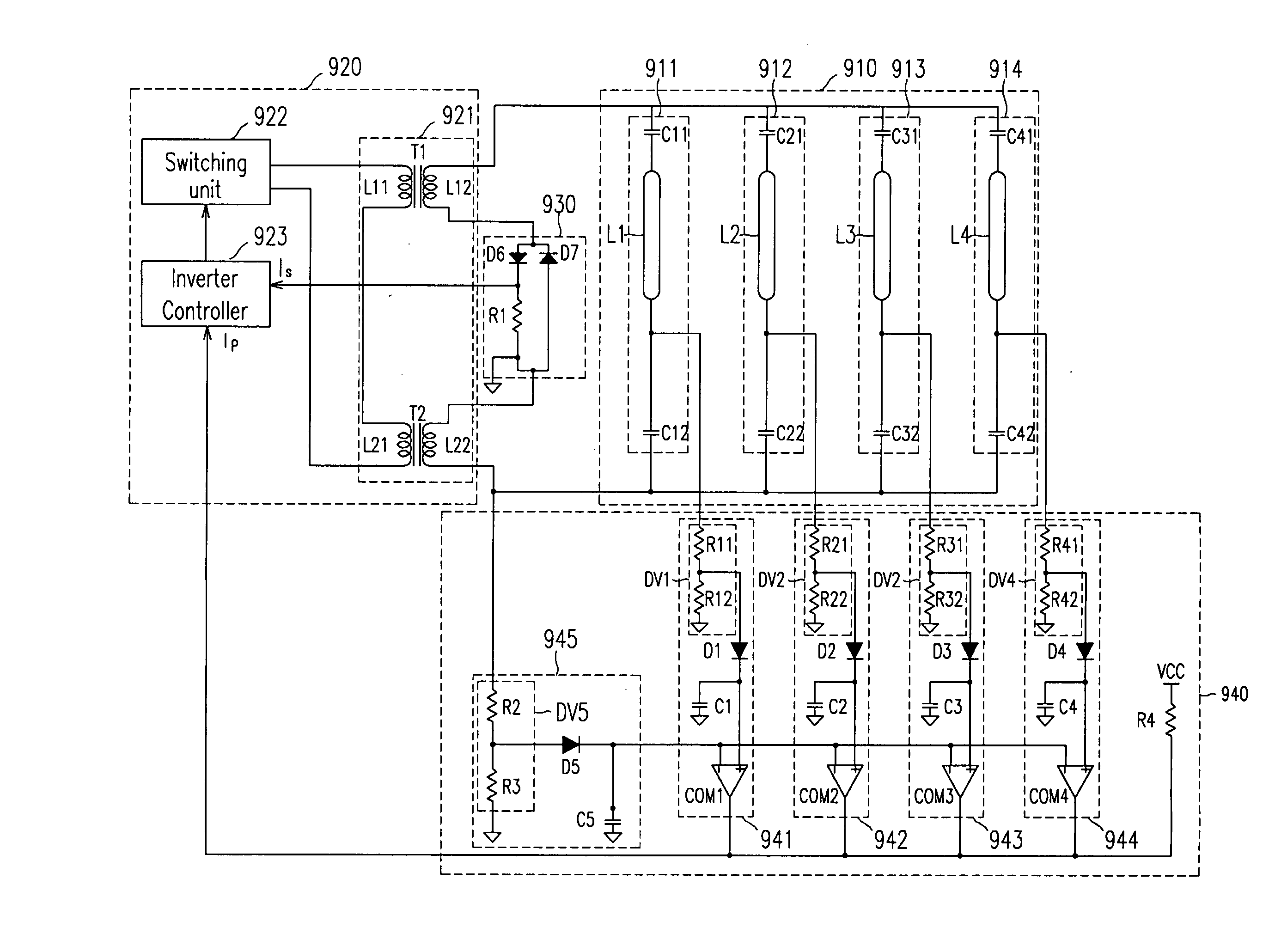
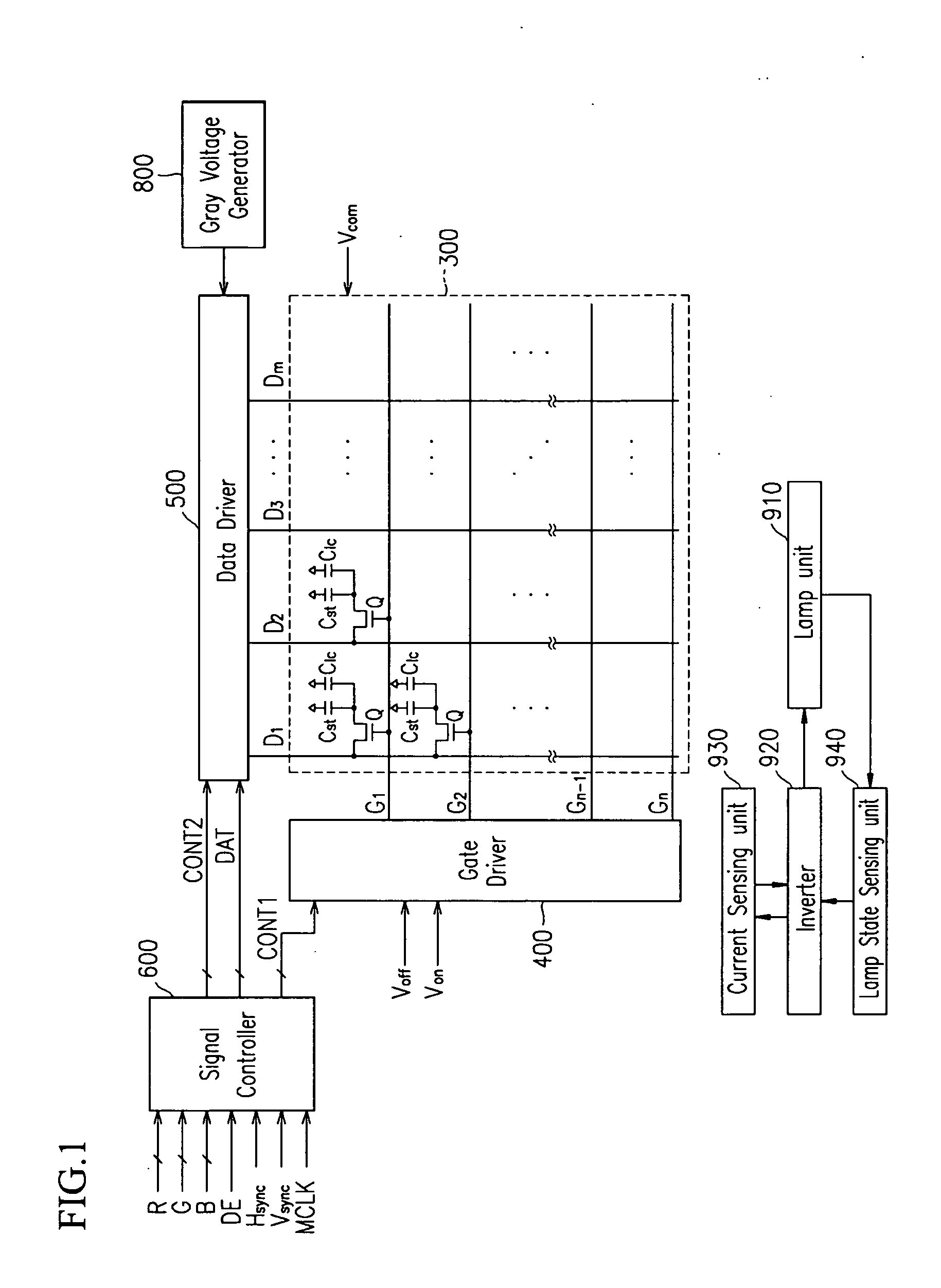
[0044] Then, a driving device of a light source for a display device according to embodiments of the present invention will be described with reference to the accompanying drawings.

[0045] A liquid crystal display according to an embodiment of the present invention is described in detail with reference to FIGS. 1-3.

[...


PUM

PropertyMeasurementUnit
voltageaaaaaaaaaa
voltageaaaaaaaaaa
voltageaaaaaaaaaa

Abstract

A driving device of a light source for a display device is provided. The light source includes a plurality of lamps connected in parallel to each other and each lamp has a first terminal and a second terminal. The driving device also includes a lamp state sensing unit sensing driving voltages applied to the respective lamps, comparing the sensed driving voltages to a reference voltage, and outputting a lamp state sensing signal having an information informing an over-current state for at least one lamp; and an inverter turning the lamps on or off by applying an AC voltage to the lamps and controlling the AC voltage based on the lamp state sensing signal. The reference voltage is varied depending on the magnitude of the driving voltages applied to the respective lamps.

Description

[0001] The present application claims priority from Korean Patent Application No. 2004-0033880, filed on May 13, 2004, the disclosure of which is hereby incorporated herein by reference in its entirety. BACKGROUND OF THE INVENTION [0002] (a) Field of the Invention [0003] The present invention relates to a driving device of a light source for a display device. [0004] (b) Description of Related Art [0005] Display devices used for monitors of computers and television sets generally include self-emitting display devices such as organic light emitting displays (OLEDs), vacuum fluorescent displays (VFDs), field emission displays (FEDs), and plasma panel displays (PDPs), and non-emitting display devices such as liquid crystal displays (LCDs) requiring external light source. [0006] An LCD includes two panels provided with field-generating electrodes and a liquid crystal (LC) layer having dielectric anisotropy and interposed therebetween. The field-generating electrodes that are supplied wit...

Claims


Application Information

Patent Timeline
Patent Type & Authority Applications(United States)
IPC IPC(8): G02F1/133H05B37/02H05B41/285
CPCY02B20/183H05B41/285Y02B20/00B01D3/40
Inventor JANG, HYEON-YONGKWON, NAM-OKKIM, MIN-GYU
Owner SAMSUNG DISPLAY CO LTD
Why Eureka
Try Eureka