Lead adaptor having low resistance conductors and/or encapsulated housing

a technology of low resistance conductors and adapters, which is applied in the direction of electrotherapy, coupling device connection, therapy, etc., can solve the problem that practitioners are unable to utilize multiple leads having different connector types with a single receptacle of an electrical therapeutic and/or diagnostic devi

Active Publication Date: 2005-12-08
OSCOR
View PDF64 Cites 127 Cited by
  • Summary
  • Abstract
  • Description
  • Claims
  • Application Information

AI Technical Summary

Benefits of technology

[0019] Any of the aforementioned embodiments of the lead adaptor may also contain means for delaying the transmission of electrical signals from the electrical therapeutic and / or diagnostic device to one or more of the endocardial leads attached to the endocardial lead adaptor, thereby allowing predetermined sequencing of electrical signal transmission to the various endocardial leads.

Problems solved by technology

Utilizing the devices currently known in the art, practitioners are unable to utilize multiple leads having different connector types with a single receptacle of an electrical therapeutic and / or diagnostic device.

Method used


Image

  • Lead adaptor having low resistance conductors and/or encapsulated housing
  • Lead adaptor having low resistance conductors and/or encapsulated housing
  • Lead adaptor having low resistance conductors and/or encapsulated housing

Examples


Embodiment Construction

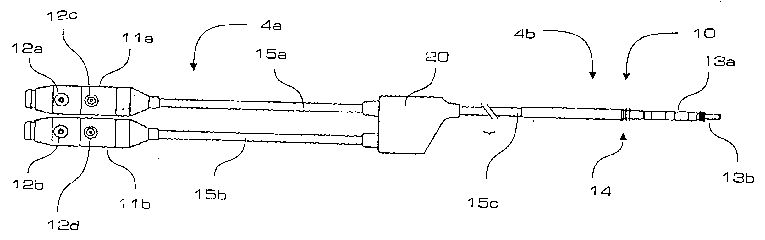
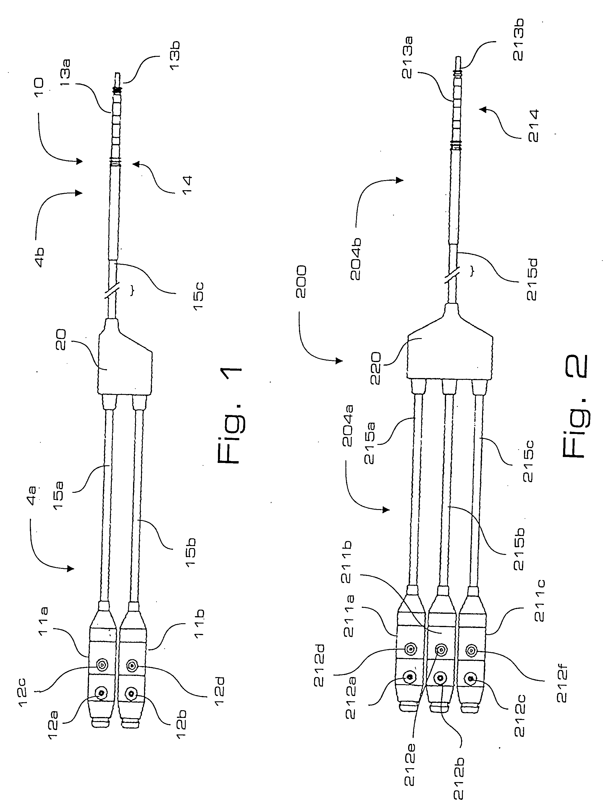
[0043] Referring now to the drawings wherein like reference numerals identify similar structural features of the several embodiments of the subject invention, there is illustrated in FIG. 1 a lead adaptor constructed in accordance with a preferred embodiment of the subject invention and designated generally by reference numeral 10. Lead adaptor 10 is a bifurcated adaptor and includes a yoke portion 20 from which depends a proximal receptacle portion 4a and a distal connector portion 4b. The receptacle portion 4a includes two receptacles 11a and 11b for operatively receiving two different types of cardiac leads. For example, the leads can have different diameters, different lengths, different shapes or different electrical contact configurations.

[0044] In embodiments of the subject invention, the receptacles of the lead adaptors can be configured to operatively accept, among other types of lead connectors, the following types of lead connectors: unipolar or bipolar IS-1 type lead co...


PUM


Abstract

An implantable lead adaptor is disclosed that includes an encapsulated thermoplastic housing defining a proximal end portion and a distal end portion. The proximal end portion has a first receptacle configured to receive a first type of connector assembly associated with a first implantable cardiac lead, and a second receptacle configured to receive a second type of connector assembly associated with a second implantable cardiac lead. An elongated flexible lead portion extends from the distal end portion of the adaptor housing. A connector assembly is operatively associated with a distal end section of the flexible lead portion of the adaptor for connection to an implantable pulse-generating device, such as, for example, an implantable pacemaker or defibrillator. Low resistance conductor wires electrically connect the connector assembly associated with the distal end section of the lead portion with the first and second receptacles of the adaptor housing.

Description

CROSS-REFERENCE TO RELATED APPLICATIONS [0001] The subject application claims the benefit of priority from U.S. Provisional Patent Application 60 / 647,736, filed Jan. 27, 2005 and is a continuation-in-part of U.S. patent application Ser. No. 10 / 174,244, filed Jun. 18, 2002, which claims the benefit of priority from U.S. Provisional Patent Application Ser. No. 60 / 337,437 filed Oct. 22, 2001, U.S. Provisional Patent Application Ser. No. 60 / 338,227 filed Dec. 6, 2001, and U.S. Provisional Patent Application Ser. No. 60 / 378,423 filed May 7, 2002, the disclosures of which are all herein incorporated by reference in their entireties.BACKGROUND OF THE INVENTION [0002] 1. Field of the Invention [0003] The subject invention is directed generally to adaptors for electrical stimulation leads, and more particularly, to adaptors for connecting cardiac leads to electrical therapeutic and / or diagnostic devices such as cardiac pacemakers and / or defibrillators. [0004] 2. Background of the Related Art...

Claims


Application Information

Patent Timeline
Patent Type & Authority Applications(United States)
IPC IPC(8): H01R12/00H01R24/58H01R31/06
CPCA61N1/056H01R24/58H01R27/02H01R2201/12H01R31/06H01R2107/00H01R31/02
Inventor OSYPKA, THOMAS P.
Owner OSCOR
Why Eureka
Try Eureka