Backlight assembly having improved heat releasing structure and display device having the same

a backlight assembly and heat releasing technology, which is applied in the direction of lighting and heating equipment, instruments, display means, etc., can solve the problems of increasing the device temperature, limited thermal energy release ability, and inability to readily release thermal energy, so as to achieve the effect of improving the heat releasing function

Inactive Publication Date: 2005-12-15
SAMSUNG DISPLAY CO LTD
View PDF12 Cites 38 Cited by
  • Summary
  • Abstract
  • Description
  • Claims
  • Application Information

AI Technical Summary

Benefits of technology

[0013] The present invention is contrived to solve the above-mentioned problems, and it is an object of the present invention to provide a backlight assembly having an improved heat releasing function.

Problems solved by technology

A disadvantage of the conventional bottom chassis structure is its limited ability for releasing the thermal energy.
Accordingly, the thermal energy cannot be readily released, thereby increasing the device temperature.
As a result, the fluorescent material of the lamps is deteriorated and the life of the lamps is reduced.
In addition, the reflecting plate is deteriorated, adversely affecting the performance of the reflecting plate, and the lamp holder is deformed due to the thermal energy generated from the lamp.
Specifically, in large LCD televisions incorporating a long lamp, current leakage and temperature difference occur between the electrodes.
The temperature difference reduces the life of the lamps.

Method used


Image

  • Backlight assembly having improved heat releasing structure and display device having the same
  • Backlight assembly having improved heat releasing structure and display device having the same
  • Backlight assembly having improved heat releasing structure and display device having the same

Examples


first embodiment

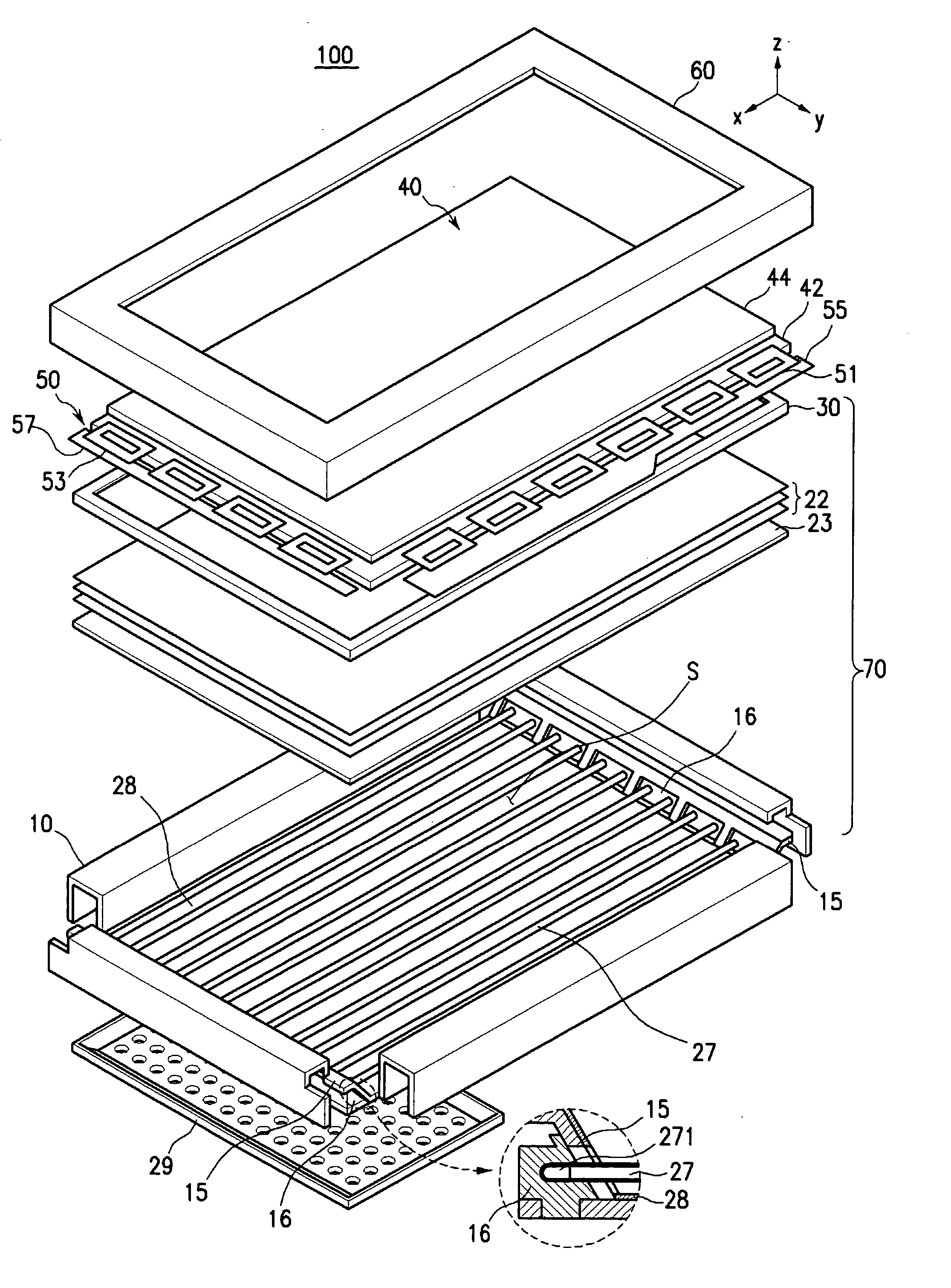
[0037]FIG. 1 shows a display device 100 having a backlight assembly 70 according to the present invention. A cross-sectional structure of a lamp holder 16 is shown in the enlarged circle of FIG. 1. The structure of the backlight assembly 70 shown in FIG. 1 is intended only to exemplify the present invention, not to limit the present invention. Therefore, the backlight assembly 70 can be modified to other structures.

[0038] The display device 100 includes a panel unit 40 displaying an image and a backlight assembly 70 supplying light to the panel unit 40. A top chassis 60 fixes the panel unit 40 onto the backlight assembly 70.

[0039] A panel unit assembly 50 includes the panel unit 40, driving IC packages 51 and 53, and printed circuit boards (PCB) 55 and 57. The panel unit assembly 50 may further include other components. A COF (Chip On Film) or TCP (Tape Carrier Package) may be used as the driving IC packages 51 and 53.

[0040] Although an LCD panel is shown as the panel unit 40 in F...

second embodiment

[0062]FIG. 7 shows an assembling process of the backlight assembly according to the present invention. As shown in FIG. 7, first, the lamp holders 26 are fixed to the fixing member 10 along with the reflecting sheet 28 and the lamps 27. Next, the separating member 25 is inserted and fixed below the lamp holders 26. The separating member 25 extends in the arrangement direction of the lamps 27, or the direction in which the multiple lamps 27 are arranged (shown as the Y axis direction in the coordinates in FIG. 7). In addition, the separating member 25 is opened in the longitudinal direction of the lamps 27.

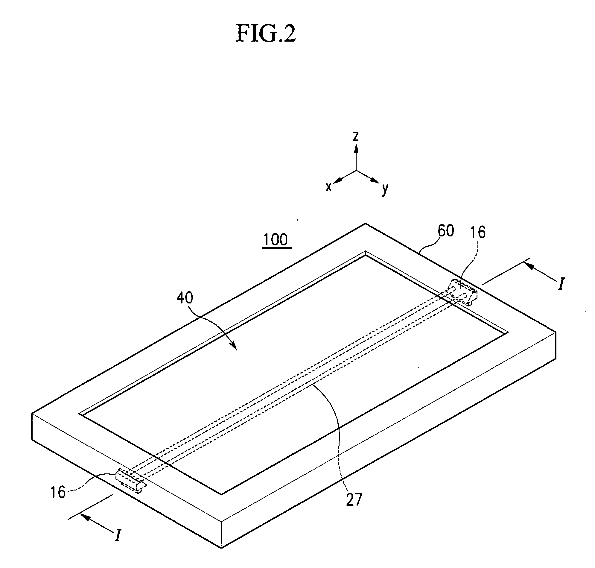
[0063]FIG. 8 is a cross-sectional view taken along Line II-II of FIG. 6. As indicated by arrows in FIG. 8, the heat is externally released from the lamp holders 26. Accordingly, it is possible to efficiently remove the heat generated from the electrodes 271 of the lamps 27.

[0064] As described above, the backlight assembly according to the present invention can prevent the delivery...


PUM

PropertyMeasurementUnit
areaaaaaaaaaaa
sizeaaaaaaaaaa
weightaaaaaaaaaa

Abstract

A backlight assembly having an improved heat releasing structure and a display device having the backlight assembly are provided. The backlight assembly includes a plurality of lamps emitting light and a fixing member receiving the plurality of lamps. A separating member protruding from an edge of the fixing member defines an inner space that contains the light-lamp portions in the fixing member, and the separating member separates electrodes of the lamps from the inner space. The separating member has openings that are positioned to direct the heat generated by the lamp electrodes away from the inner space where the excess heat can cause display quality deterioration.

Description

CROSS-REFERENCE TO RELATED APPLICATION [0001] The present application claims priority to Korean patent application No. 2004-0043463 filed in the Korean Intellectual Property Office on Jun. 14, 2004, the content of which is herein incorporated by reference in its entirety. BACKGROUND OF THE INVENTION [0002] (a) Field of the Invention [0003] The present invention relates to a backlight assembly having an improved heat releasing structure and a display device having the backlight assembly, and more particularly to a backlight assembly that can efficiently release the heat generated from lamp electrodes to an area external to the assembly and a display device having the backlight assembly. [0004] (b) Description of the Related Art [0005] Due to the recent drastic development of semiconductor technologies, the demand for display devices of a small size, light weight, and improved performance has explosively increased. [0006] Liquid crystal display (LCD) devices, which employ an LCD panel...

Claims


Application Information

Patent Timeline
Patent Type & Authority Applications(United States)
IPC IPC(8): F21V7/04G02F1/13357
CPCG02F2001/133628G02F1/133604G02F1/133628G02F1/1335
Inventor RYU, HO-HAN
Owner SAMSUNG DISPLAY CO LTD
Why Eureka
Try Eureka