Incontinence sling

a sling and incontinence technology, applied in the field of incontinence slings, can solve the problems of not always being able to establish the proper sling tension, disproportionate and overwhelming number of women suffering from incontinence,

Inactive Publication Date: 2005-12-22
STOUT MEDICAL GROUP
View PDF5 Cites 246 Cited by
  • Summary
  • Abstract
  • Description
  • Claims
  • Application Information

AI Technical Summary

Problems solved by technology

Although significant numbers of men are afflicted, women suffer-from this disorder in disproportionate and overwhelming numbers.
Urge incontinence occurs when one has the need to urinate but is unable to prevent leakage until proper facilities are reached.
There are several disadvantages to this device.
It is not always possible to establish the proper sling tension.
Too much tension means that it will be difficult, if not impossible, for the person to urinate using muscular contractions that compress the bladder.
Too little tension means that the disorder remains uncorrected despite the person having undergone the procedure.
It is, furthermore, difficult to adjust the tension once the sling is implanted.
Adjustment is desirable because over time, the muscles and other tissue of the abdomen change in their compliance, strength and tone, and what may be sufficient tension at one point in time may be too much or too little later, leading to problems which must again be addressed by invasive surgery.
Probably the worst problem associated with slings currently in use is known as “erosion”, whereby, in response to normal movement and pressure of the abdominal muscles, the edge of the sling, being relatively sharp, cuts through the abdominal tissue and enters the urethra.

Method used


Image

  • Incontinence sling
  • Incontinence sling
  • Incontinence sling

Examples


Embodiment Construction

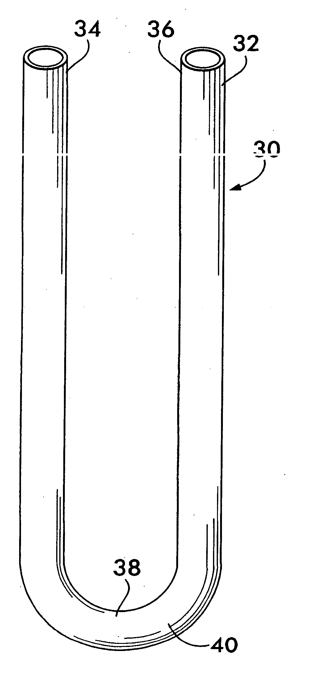
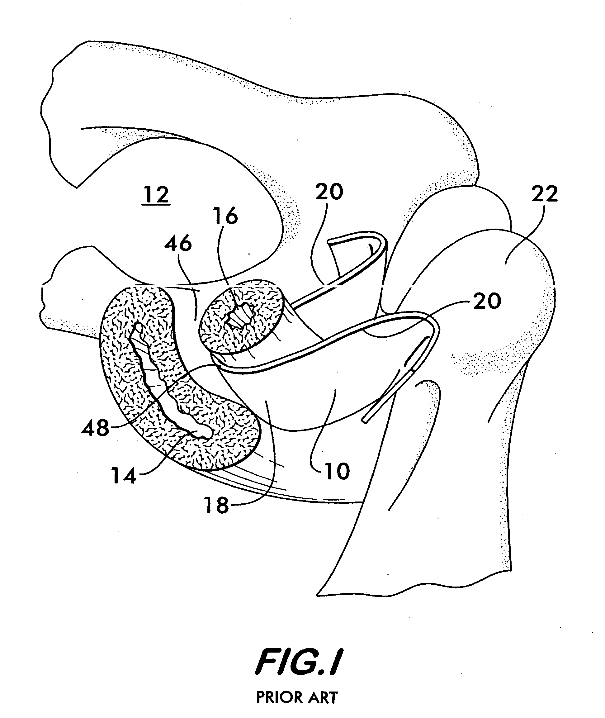
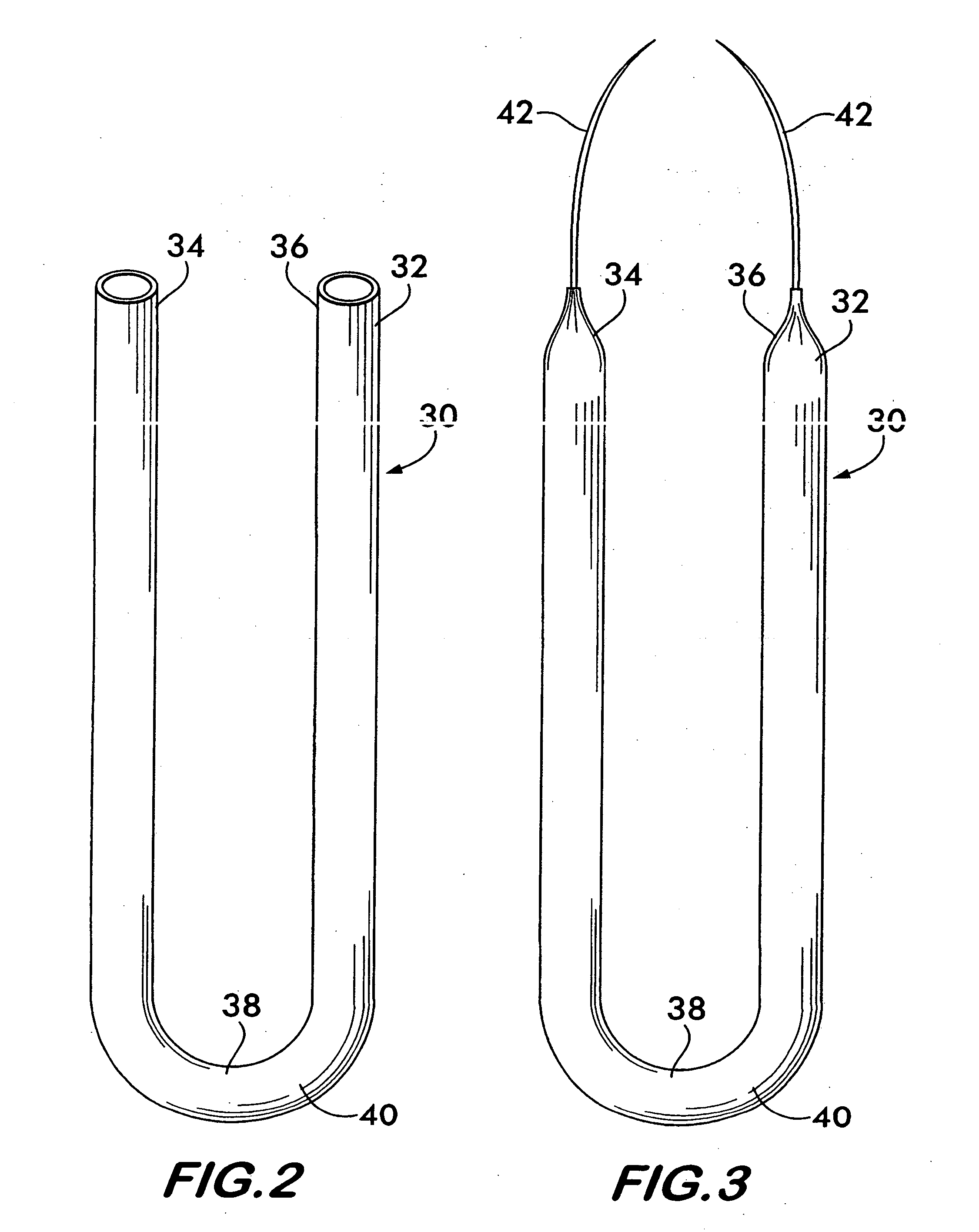
[0022]FIG. 2 shows an incontinence sling 30 according to the invention. Sling 30 comprises an elongated flexible tube 32 having opposite end portions 34 and 36. An intermediate portion 38 is positioned between end portions 34 and 36. The intermediate portion 38 is bendable to form a substantially U-shaped cradle 40 positionable adjacent to the urethra 16 as shown in FIGS. 4 and 5. End portions 34 and 36 are positionable so as to extend through the abdomen 12 away from the vagina 14. The end portions 34 and 36 anchor the sling 30 in position within the abdomen as described in detail below.

[0023] End portions 34 and 36 are substantially inextensible lengthwise, especially in comparison with center portion 38, which is lengthwise elastically extensible. By varying the longitudinal stiffness as a function of position along the sling 30 it is possible to achieve better control over the transverse compressive force applied to the urethra and thereby avoid the aforementioned problems asso...


PUM


Abstract

A sling for controlling urinary incontinence is disclosed. The sling is formed from a tube having substantially lengthwise inextensible end portions and an elastically lengthwise extensible intermediate portion between the end portions. The intermediate portion has a U-shape which cradles the urethra. The end portions extend through the abdominal tissue to anchor the intermediate portion in position. The sling places the urethra under a transverse compressive load to hold it closed and prevent inadvertent urination. The tube is formed from interlaced filamentary members. Interlacing may be by warp knitting, weaving using a leno weave or braiding using a tri-axial braid structure. The end portions have a rough texture to facilitate anchoring in the tissue of the abdominal wall. The intermediate portion is smooth and soft to prevent tissue erosion.

Description

FIELD OF THE INVENTION [0001] This invention relates to a device implantable within the abdomen to treat urinary incontinence. BACKGROUND OF THE INVENTION [0002] In the United States, more than 13 million people suffer from the effects of urinary incontinence. Although significant numbers of men are afflicted, women suffer-from this disorder in disproportionate and overwhelming numbers. [0003] Some factors which lead to incontinence in women include the effects of childbirth, hysterectomies, urinary tract infections, relaxation of the pelvic muscles and the thinning of urethral tissue associated with hormone reduction during menopause. These factors contribute to a weakening of the urinary sphincter muscles (located beneath the bladder surrounding the urethra) which may lead to “stress incontinence”, “urge incontinence” or a mixture of both types of incontinence. Stress incontinence is associated with the involuntary leakage of urine due to increased pressure on the bladder occasion...

Claims


Application Information

Patent Timeline
Patent Type & Authority Applications(United States)
IPC IPC(8): A61F2/00A61F2/02
CPCA61F2250/0018A61F2/0045
Inventor GREENHALGH, E. SKOTT
Owner STOUT MEDICAL GROUP
Why Eureka
Try Eureka