Liquid ejection head, liquid ejection apparatus, and drive control method

a technology of liquid ejection and liquid ejection, which is applied in the direction of printing, inking apparatus, other printing apparatus, etc., can solve the problems of lowering the ejection speed (ejection frequency), and achieve the effect of not significantly increasing the refill time and increasing the volume of the pressure chamber

Inactive Publication Date: 2006-02-02
FUJIFILM CORP
View PDF9 Cites 18 Cited by
  • Summary
  • Abstract
  • Description
  • Claims
  • Application Information

AI Technical Summary

Benefits of technology

[0035] According to the present invention, in the case of refilling where liquid is supplied to the pressure chamber through the supply port after the liquid is ejected from the nozzle, the relationship among the inertance Mn of the nozzle, the liquid resistance Rn of the nozzle, the compliance Cn caused by the surface tension of the liquid inside the nozzle, the inertance Ms of the supply port, and the liquid resistance Rn of the supply port is determined so that the meniscus surface located in the vicinity of the nozzle does not oscillate, thus a predetermined ejection frequency can be maintained without increasing the refill time.
[0036] Moreover, the volume of the pressure chamber is increased more than its initial state of before an ejection operation, and the pressurizing device is controlled so as to return the volume of the pressure chamber to the volume of its initial state after a lapse of a predetermined time. Therefore, the refill time is not increased significantly due to an impact of the viscosity resistance when using highly viscous liquid, and a predetermined ejection cycle can be secured.

Problems solved by technology

Since the time for waiting until refilling is completed becomes long, this time for waiting is the rate-controlling factor, thus the problem is that the ejection speed (ejection frequency) is lowered.

Method used


Image

  • Liquid ejection head, liquid ejection apparatus, and drive control method
  • Liquid ejection head, liquid ejection apparatus, and drive control method
  • Liquid ejection head, liquid ejection apparatus, and drive control method

Examples


Embodiment Construction

General Composition of Inkjet Recording Apparatus

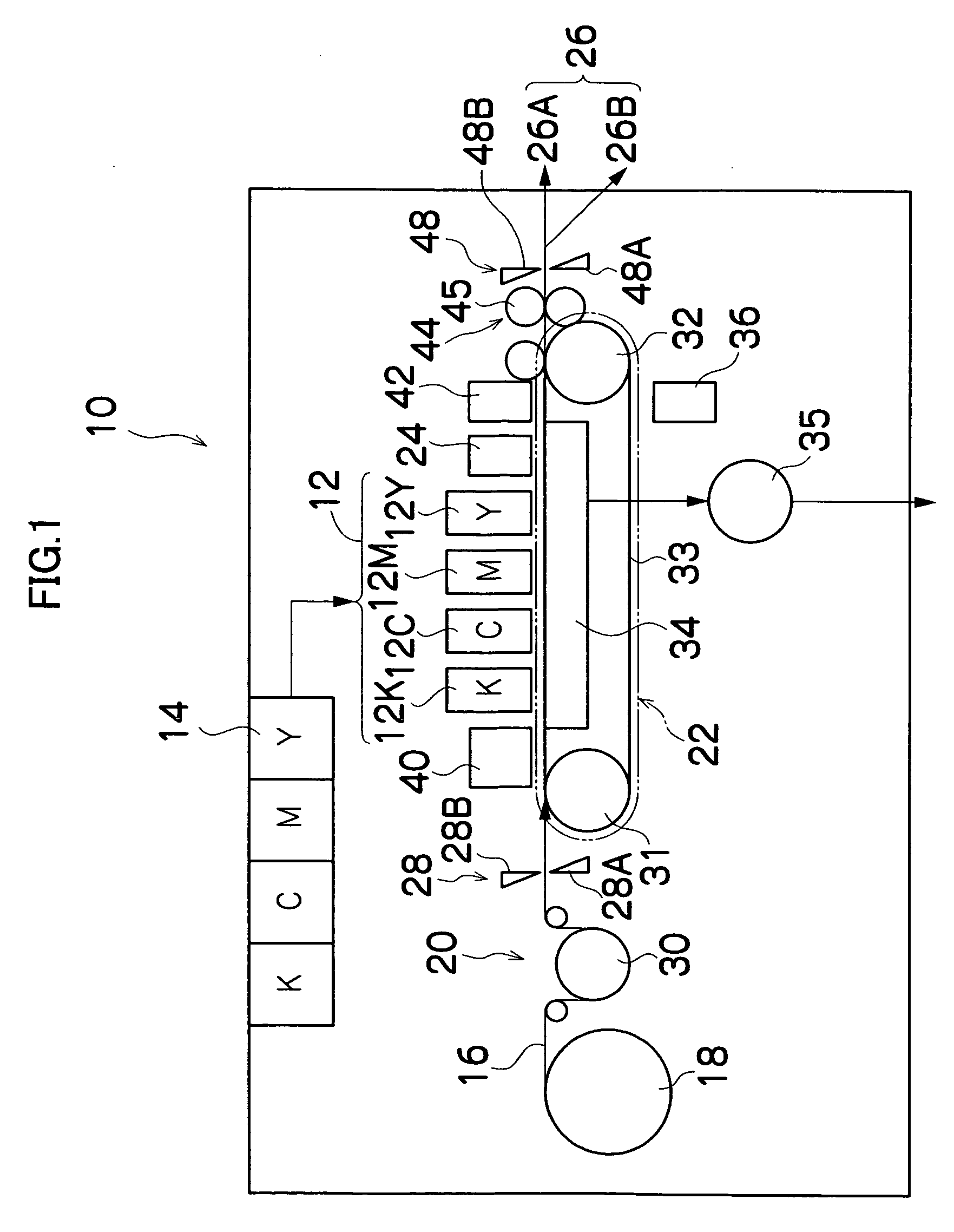
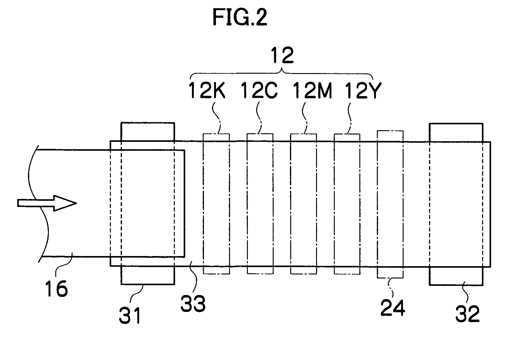
[0048]FIG. 1 is a diagram of the general composition of an inkjet recording apparatus according to an embodiment of the present invention. As shown in FIG. 1, the inkjet recording apparatus 10 comprises: a printing unit 12 having a plurality of inkjet heads 12K, 12C, 12M and 12Y provided for ink colors of black (K), cyan (C), magenta (M) and yellow (Y), respectively; an ink storing and loading unit 14 for storing inks of K, C, M and Y to be supplied to the print heads 12K, 12C, 12M and 12Y; a paper supply unit 18 for supplying recording paper 16; a decurling unit 20 removing curl in the recording paper 16; a suction belt conveyance unit 22 disposed facing the nozzle face (ink-droplet ejection face) of the print unit 12, for conveying the recording paper 16 while keeping the recording paper 16 flat; a print determination unit 24 for reading the printed result produced by the printing unit 12; and a paper output unit 26 for outputting...


PUM


Abstract

The liquid ejection head comprises: a nozzle through which liquid is ejected; a pressure chamber which stores the liquid ejected through the nozzle; a pressurizing device which changes a volume of the pressure chamber to apply pressure to the liquid stored in the pressure chamber; and a supply port through which the liquid is supplied to the pressure chamber, wherein the liquid ejection head has a structure such that inertance Mn of the nozzle, liquid resistance Rn of the nozzle, compliance Cn caused by a surface tension of the liquid in the nozzle, inertance Ms of the supply port, and liquid resistance Rn of the supply port satisfy the following inequality: 4·(Mn+Ms)Cn(Rn+Rs)2,
so that oscillation of a meniscus surface located in vicinity of the nozzle is controlled at a time of refill when the liquid is filled in the pressure chamber through the supply port after the liquid is ejected from the nozzle.

Description

BACKGROUND OF THE INVENTION [0001] 1. Field of the Invention [0002] The present invention relates to a liquid ejection head, a liquid ejection apparatus, and a drive controlling method, more particularly to a structure and an ejection control technology of a liquid ejection head which is used in an inkjet recording apparatus and the like. [0003] 2. Description of the Related Art [0004] As an example of an image forming apparatus, there is known an inkjet recording apparatus which has an inkjet head (ejection head) having disposed multiple nozzles (ejection elements) therein, and forms an image on a medium (ejection receiving medium) by ejecting ink from the nozzles while relatively moving the inkjet head and the medium. [0005] For an ink ejection method in an inkjet head of an inkjet recording apparatus, there is known a piezoelectric method where a diaphragm (pressure plate) constituting a part of a pressure chamber is deformed by deformation of a piezoelectric element to change th...

Claims


Application Information

Patent Timeline
Patent Type & Authority Applications(United States)
IPC IPC(8): B41J2/06
CPCB41J2/04543B41J2/04581B41J2/04588B41J2202/21B41J2002/14459B41J2202/11B41J2202/20B41J2/14233
Inventor MATAKI, HIROSHI
Owner FUJIFILM CORP
Why Eureka
Try Eureka