Coaxial connector with center conductor seizure

a center conductor and coaxial connector technology, applied in the direction of connections, basic electric elements, electric devices, etc., can solve the problems of high installation burden, complexity of such connectors, and relatively high parts coun

Active Publication Date: 2006-02-23
CORNING CABELCON
View PDF69 Cites 9 Cited by
  • Summary
  • Abstract
  • Description
  • Claims
  • Application Information

AI Technical Summary

Benefits of technology

[0017] Briefly described, and in accordance with a preferred embodiment thereof, the present invention provides a connector consisting of a back nut, inner and outer terminals, and insulator. The back nut is made of a single tubular piece and does not enclose any further parts, except perhaps a sealing ring. In connecting a coaxial cable to the connector, the cable is inserted through the back nut, and a portion of the outer conductor at the end of the cable is flared and shaped along the back nut. The back nut is then axially displaced to clamp the end of the outer conductor of the coaxial cable between an outer terminal, or outer body, of the coaxial connector and the back nut. This process is very simple and easy to carry out, while greatly reducing the chances of errors and defects in assembly and mounting in comparison to conventional connectors.

Problems solved by technology

In addition, reliable coaxial connectors must form a secure mechanical connection to the end of the coaxial cable, since mechanical separation of the connector from the end of the cable will interfere with successful transmission of the desired electrical signal.
However, the complexity of such connectors, their relatively high parts count, and the burden imposed upon the technician during installation, are all significant for such known coaxial connectors.
The large number of moving parts in the back nut portion complicates the fitting of a coaxial cable which usually requires the use of several specialized tools.
Additionally, the risk of connector malfunctioning and mounting problems increases with a higher number of moving parts, since there is a greater chance that at least one part may be defective, missing or incorrectly attached.
Due to the large number of moving parts encapsulated in the back nut of most conventional connectors, the outer conductor must be thoroughly cleared of all glue and adhesive material that may hinder or jam the parts during mounting and tightening, or a poor electrical connection may result.
This process can prove to be quite difficult and time-consuming.
The manufacture and assembly of conventional connectors is also expensive in terms of time taken and material costs due to the number of parts enclosed in the back nut, which have to be manufactured and assembled.

Method used


Image

  • Coaxial connector with center conductor seizure
  • Coaxial connector with center conductor seizure
  • Coaxial connector with center conductor seizure

Examples


second embodiment

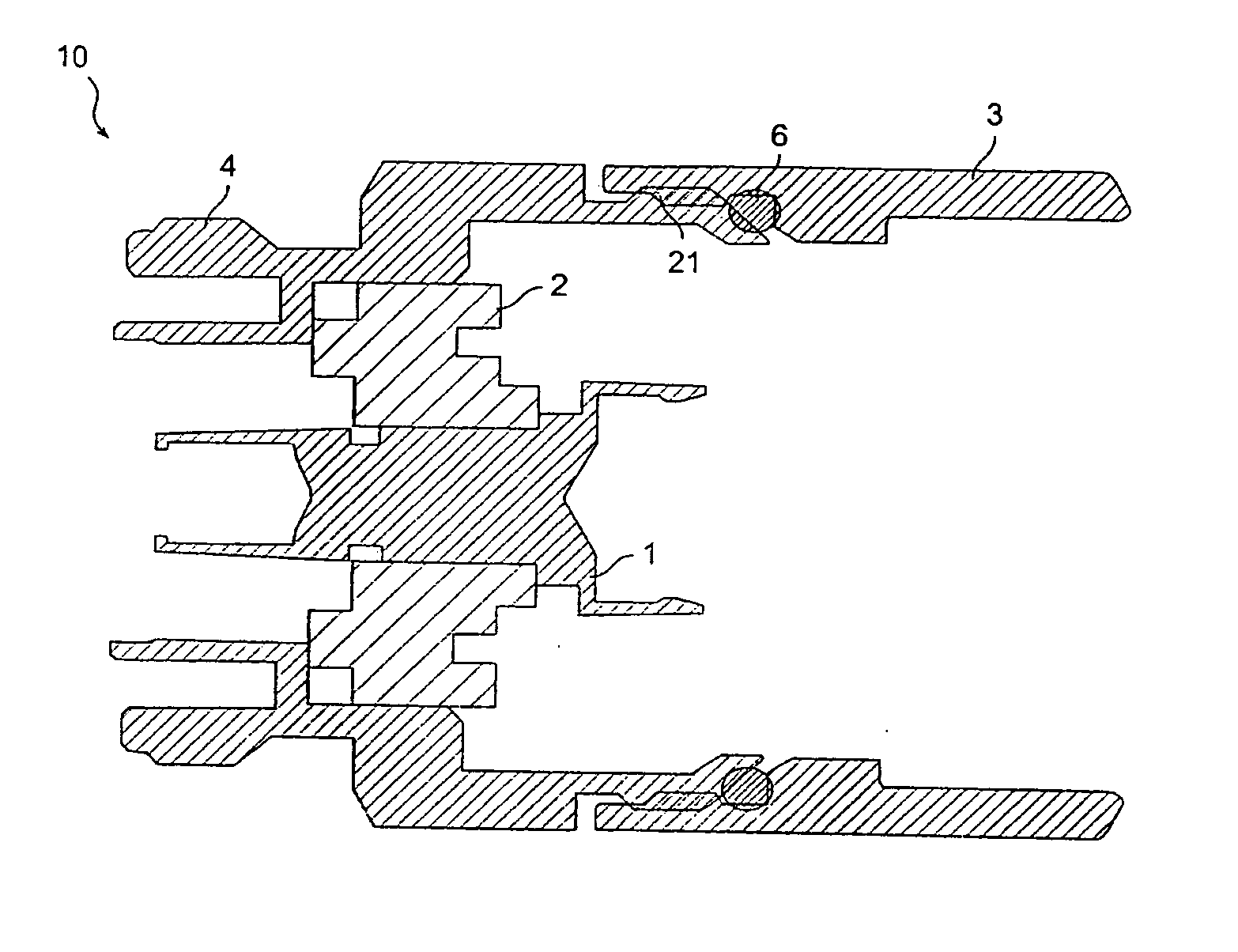
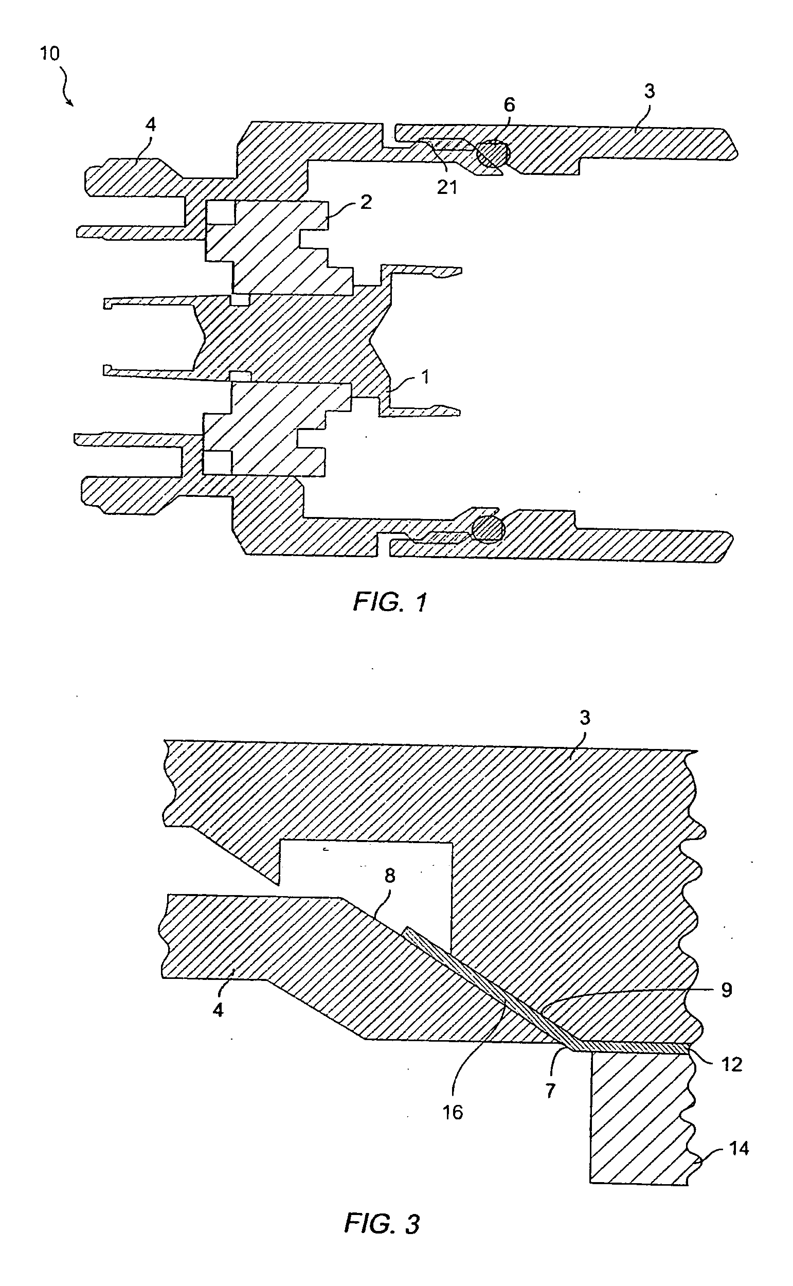
[0043] the coaxial cable may be mounted to coaxial connector 10 without removing either jacket 14 or dielectric 13. The steps for mounting the cable to coaxial connector 10 according to this method, are as follows: first, an end portion of the cable is inserted through back nut 3. A tool is then used to pry the end portion of outer conductor 12 away from dielectric 13, and to flare the end of outer conductor 12 outwardly, as mentioned above. The inner conductor of the coaxial cable is then inserted into inner terminal 1 of the connector as described above, and back nut 3 is screwed over outer terminal 4 until there is a mechanical stop, leaving the end portion of the cable securely clamped between faces 8 and 9 of the outer terminal 4 and back nut 3. The cable can be mounted according to this method as long as there is a sufficient contact between the outer conductor portion 7 and face 8 of outer terminal 4.

third embodiment

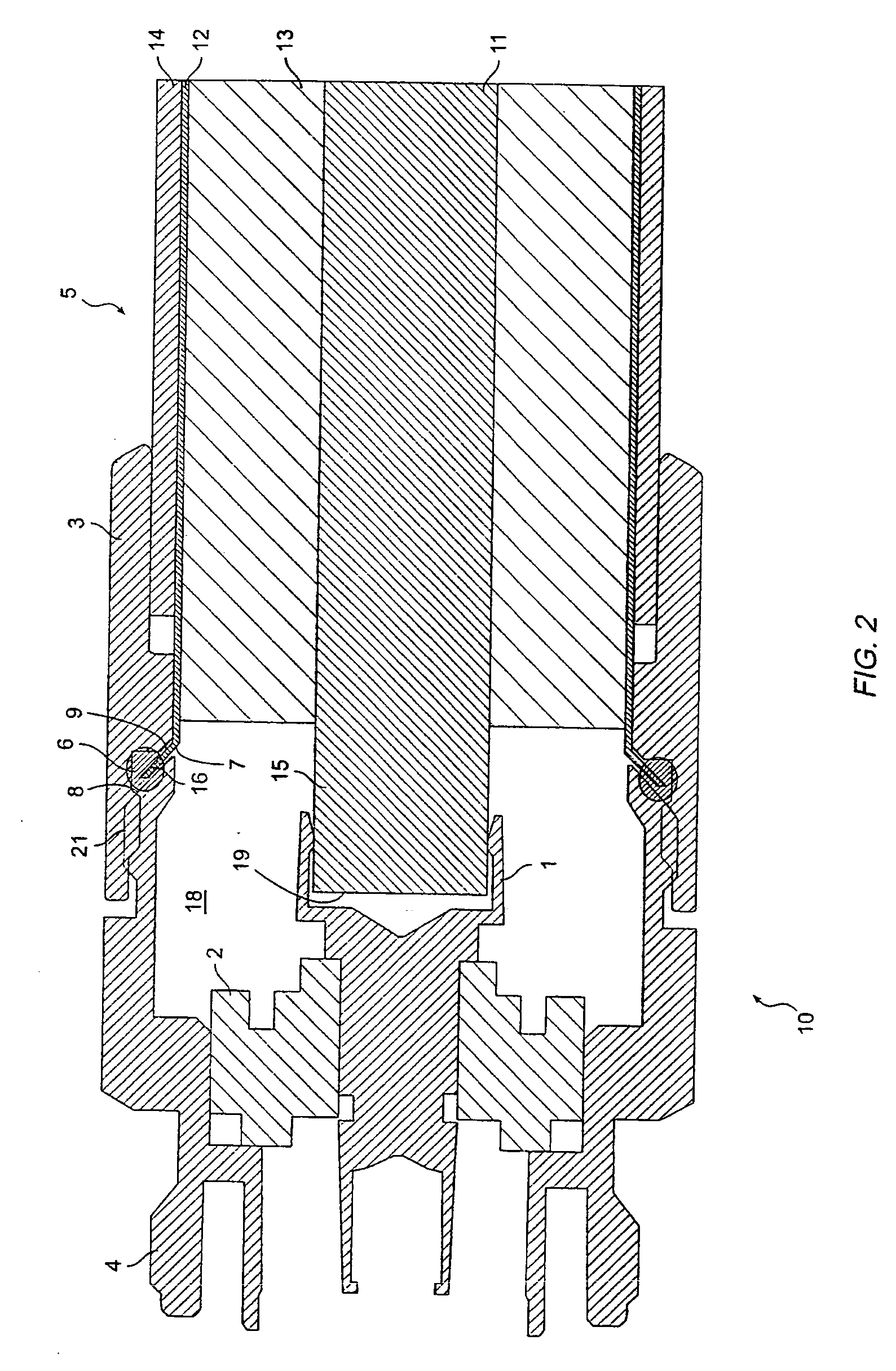
[0044] the cable is mounted by removing the dielectric within the exposed end of the coaxial cable, but not the cable jacket. This is a combination of the two previous embodiments. The steps for mounting the cable are as follows: first, a sufficient amount of dielectric material 13 is removed from the end portion of cable 5. The exposed end of coaxial cable 5 is then inserted through the central aperture of back nut 3. The end portion 7 of outer conductor 12 is again flared outwardly. The inner conductor 15 of coaxial cable 5 is then inserted into inner terminal 1 of connector 10, as described above. The back nut 3 is then longitudinally displaced, as by screwing back nut 3 onto outer terminal 4, so that the flared outer conductor and adjoined insulating jacket are clamped securely between the outer terminal's contact face 8 and the abutting back nut face 9.

[0045] Turning to FIG. 4, a coring tool and cooperating collar are shown for removing foam dielectric from between the inner c...


PUM


Abstract

A coaxial connector includes a removable back nut, an outer body, and a center conductor supported within the outer body by a dielectric. The center conductor includes a female socket for receiving an exposed inner conductor of a coaxial cable, and a compression member compresses the female socket to seize the inner conductor as the back nut is secured to the outer body. In use, a prepared end of a coaxial cable is inserted through the back nut, and the end portion of the outer conductor of the coaxial cable is flared outwardly. As the back nut is tightened onto the outer body, the flared end of the outer conductor is directly clamped between integral clamping surfaces of the back nut and outer body. As the back nut is tightened, the compression member simultaneously engages the female socket to seize the inner conductor.

Description

TECHNICAL FIELD [0001] The present invention relates generally to a coaxial connector for hardline coaxial cables, and more particularly, to a simplified coaxial connector and method of attachment of a coaxial cable to the coaxial connector. BACKGROUND OF THE INVENTION [0002] Hardline coaxial cables are widely used in the cable television industry to distribute cable television signals. Such cables include a central inner conductor surrounded by a low loss, high dielectric plastic foam. The foam dielectric is, in turn, surrounded by a metallic outer conductor which may be cylindrical or corrugated. A protective insulating jacket, or sheath, surrounds the metallic outer conductor and helps prevent moisture from degrading the signal path. The ends of such coaxial cables must be connected to junction boxes, amplifiers, and other coaxial ports, and coaxial connectors are well known for terminating the ends of hardline coaxial cables. [0003] In order to properly transmit an electrical si...

Claims


Application Information

Patent Timeline
Patent Type & Authority Applications(United States)
IPC IPC(8): H01R9/05
CPCH01R9/0521
Inventor HENNINGSEN, JIMMY CIESLA
Owner CORNING CABELCON
Why Eureka
Try Eureka