Dust collection unit and vacuum cleaner with the same

Active Publication Date: 2006-03-02
LG ELECTRONICS INC
View PDF5 Cites 44 Cited by
  • Summary
  • Abstract
  • Description
  • Claims
  • Application Information

AI Technical Summary

Benefits of technology

[0019] According to the present invention, since the foreign objects clogging the outer surface of the porous filter unit can be effectively removed, the air effectively flows, thereby improving the dust removal efficiency of the vacuum cleaner

Problems solved by technology

At this point, dirt particles may clog the surface of the porous filter unit.
Furthermore, the motor may be overloaded.
When the dirt particles are tightly

Method used


Image

  • Dust collection unit and vacuum cleaner with the same
  • Dust collection unit and vacuum cleaner with the same
  • Dust collection unit and vacuum cleaner with the same

Examples


Example

[0025] Reference will now be made in detail to the preferred embodiments of the present invention, examples of which are illustrated in the accompanying drawings. Wherever possible, the same reference numbers will be used throughout the drawings to refer to the same or like parts.

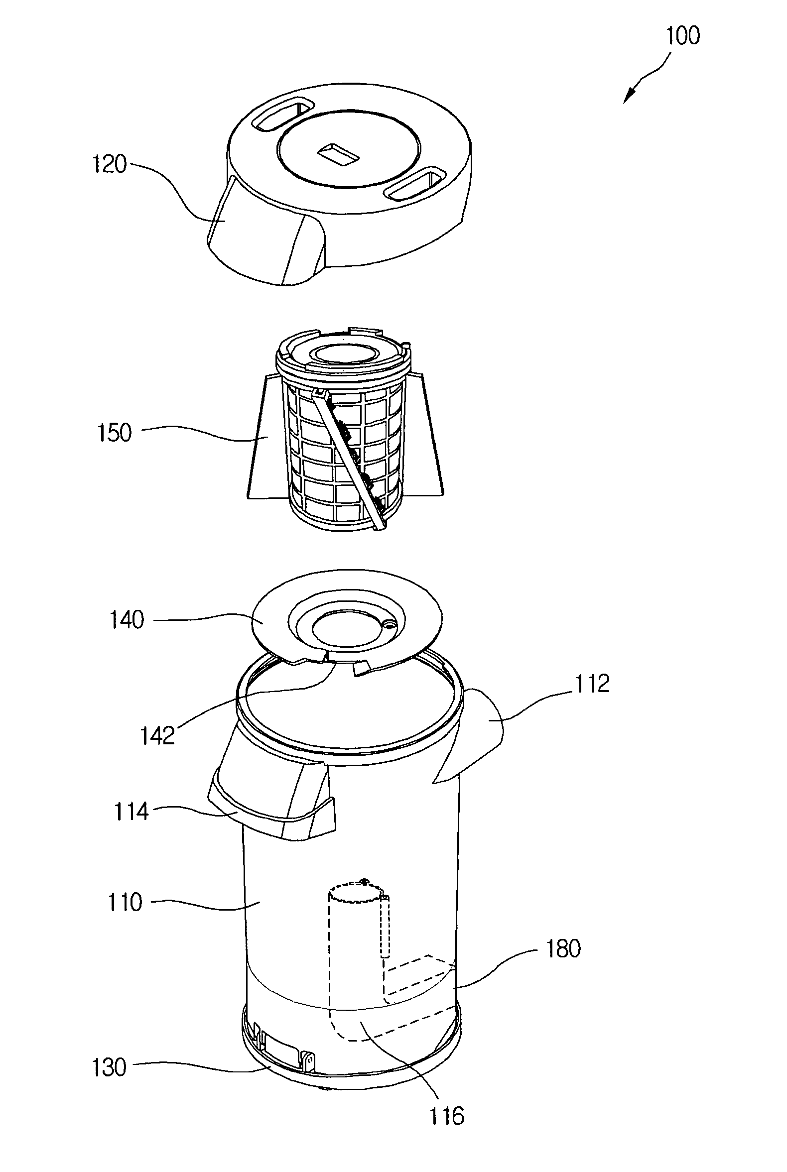
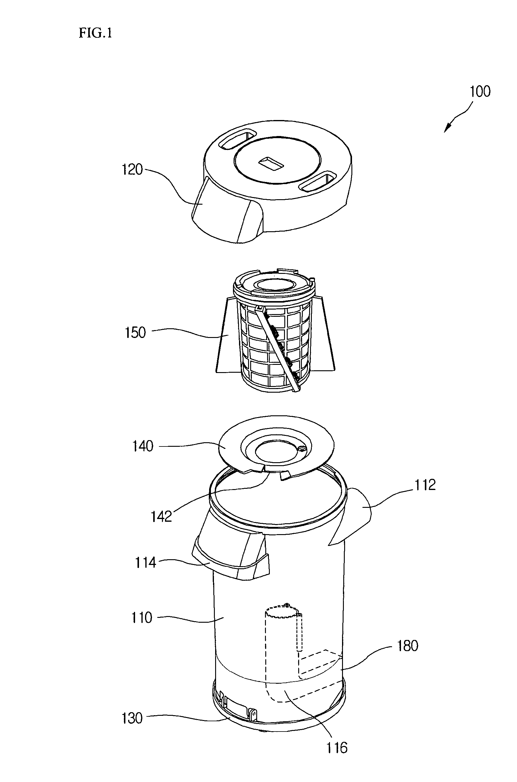
[0026]FIG. 1 shows a dust collection unit according to an embodiment of the present invention.

[0027] Referring to FIG. 1, the inventive vacuum cleaner includes a dust collection container 110 and upper and lower cover 120 defining a top and bottom of the dust collection container 110. A suction guide 112 is provided on a portion of an outer circumference of the dust collection container 110. The suction guide extends from the outer circumference of the dust collection container 110 to guide the air into the dust collection container 110 along an inner wall of the dust collection container 110 in a tangential direction. In addition, the suction guide 112 extends along an outer surface tangential line of th...


PUM

PropertyMeasurementUnit
Forceaaaaaaaaaa
Widthaaaaaaaaaa
Distanceaaaaaaaaaa

Abstract

A dust collection unit for a vacuum cleaner includes a dust collection container for collecting foreign objects contained in air introduced therein, covers defining a top and bottom of the dust collection container, and a filter-cleaning unit having a plurality of brushes rotating around the porous filter unit to remove the foreign objects clogging the outer surface of the porous filter unit.

Description

BACKGROUND OF THE INVENTION [0001] 1. Field of the Invention [0002] The present invention relates to a vacuum cleaner, and particularly, to a dust collection unit for a vacuum cleaner, which can automatically remove foreign objects clogging the filter unit. More particularly, the present invention relates to a dust collection unit for a vacuum cleaner, which can efficiently remove foreign objects adhered to a surface of a porous filter unit while air passes through the dust collection unit and reduce noise generated during the cleaning of the porous filter unit. [0003] 2. Description of the Related Art [0004] A vacuum cleanser is classified into a canister type and an upright type. The former includes a suction nozzle unit sucking air containing foreign object while moving along a floor, a main body with a unit for generating air suctioning force through the suction nozzle unit, a dust collection unit for filtering foreign object contained in the air sucked into the main body, and a...

Claims


Application Information

Patent Timeline
IPC IPC(8): B01D50/00
CPCA47L9/20A47L9/0081Y10S55/02Y10S55/03
Inventor LEE, CHANG OOKCHOI, JAE WON
Owner LG ELECTRONICS INC
Why Eureka
Try Eureka