

System, apparatus and method for screening personnel
- Summary
- Abstract
- Description
- Claims
- Application Information
AI Technical Summary
Benefits of technology
Problems solved by technology
Method used
Image

Examples
Embodiment Construction
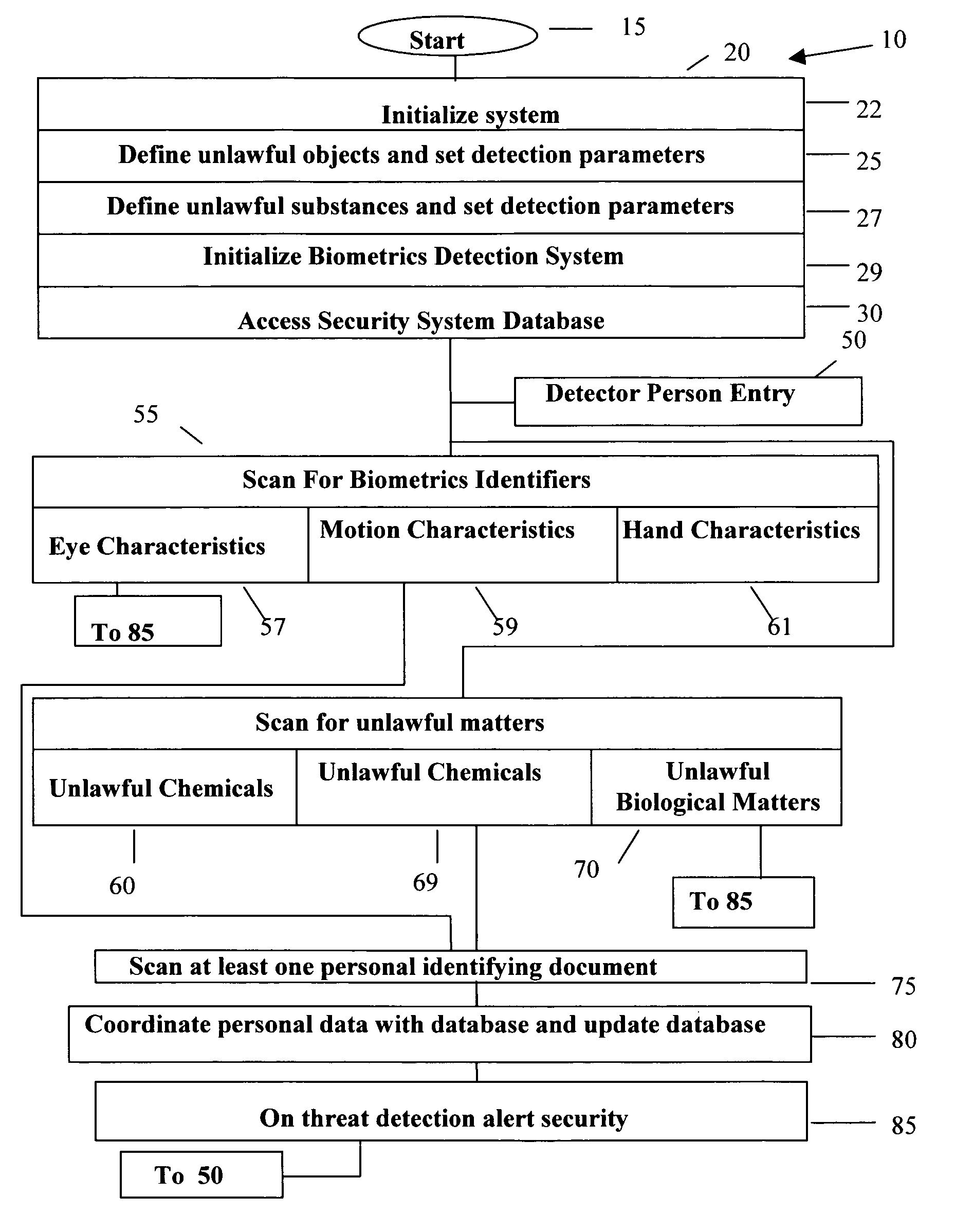
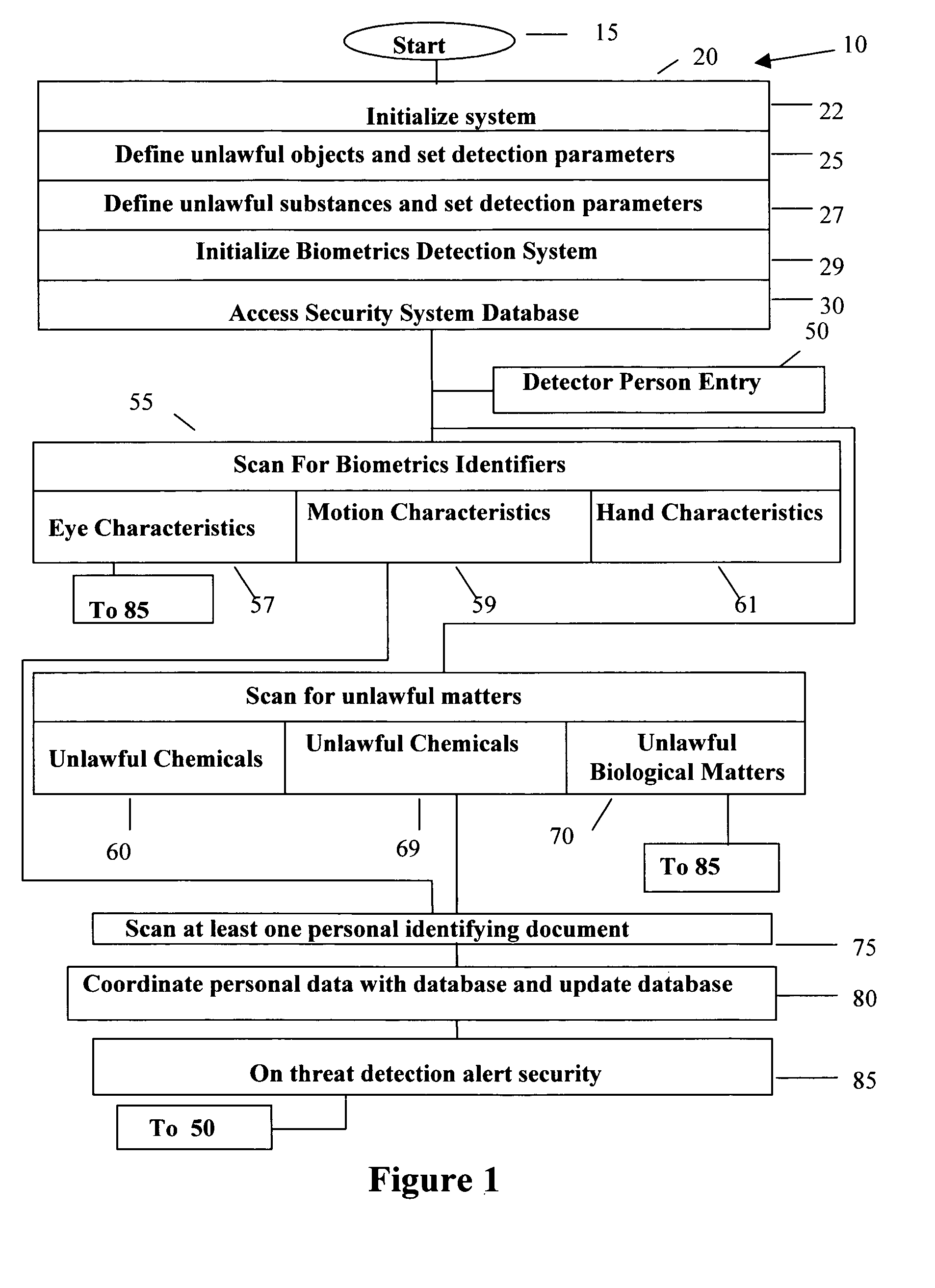
[0027] The observation that heightened security environment requires significantly increased screening of the personnel, which in turn causes significant delays and raised tempers amongst, for example, traveling public and possibly screening personnel. Such screening process not only causes delays for everyone, it results in diminished quality of surveillance. This diminished quality of surveillance results in enormous economic losses in terms of time and resources to, for example, airlines, related industries. The losses cascade throughout the economic ladder. In addition, most screening systems are not comprehensive and require frequent secondary screening like, for example, feet screening and body pat searches. These body pat searches are generally perceived to be too intrusive by the people and at times have been reported in the media to be abused by the security personnel.
[0028] Therefore, improved techniques for screening and corresponding apparatus are highly desirable where...
PUM
 Abstract
Description
Claims
Application Information