

Image recording sheet moistening device and image printing apparatus
a technology of moistening device and image printing, which is applied in the direction of office printing, instruments, coatings, etc., can solve the problem of uneven moistening recovery
- Summary
- Abstract
- Description
- Claims
- Application Information
AI Technical Summary
Benefits of technology
Problems solved by technology
Method used
Image

Examples
first embodiment
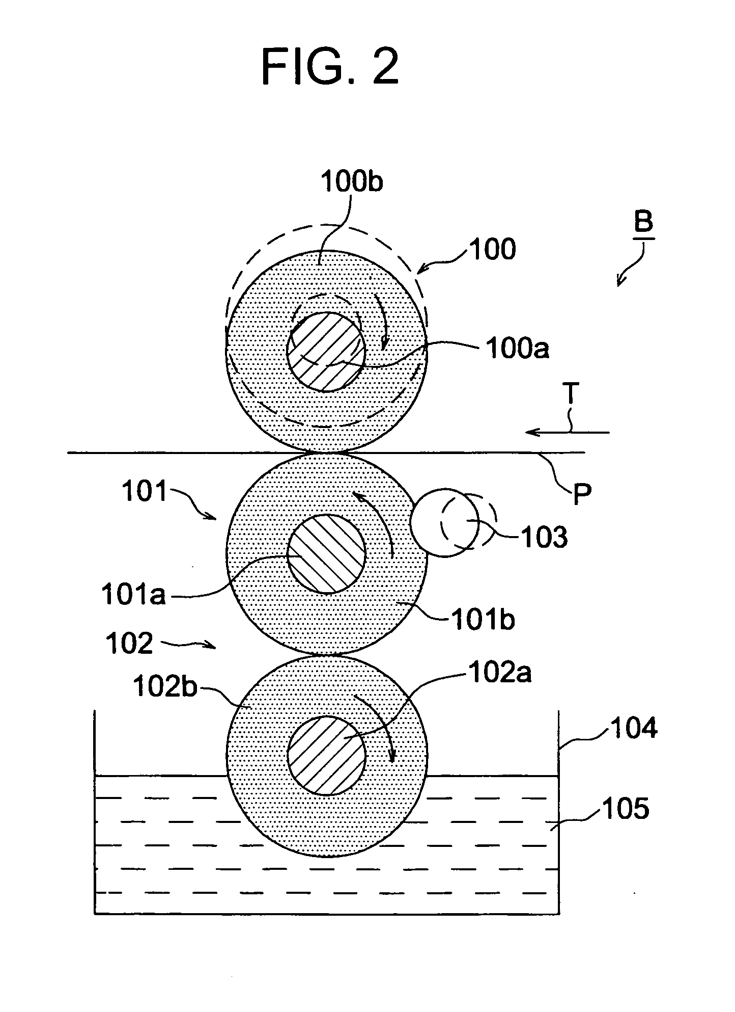
[0045]FIG. 2 is a schematic sectional view showing the moistening device B according to the present invention.
[0046] Referring to FIG. 2, reference numerals 100 and 101 denote moistening rollers which supply moisture to the sheet. The moistening rollers 100 and 101 are respectively obtained by forming porous layers 100b and 101b formed of porous urethane rubber or the like on shaft cores 100a and 101b made of rigid bodies such as a metal, hard resin, or the like. Both the porous layers 100b and 101b form porous surface layers which receive supplied water through their surfaces and supply moisture to the sheet P to moisten it. Reference numeral 102 denotes a dampening roller serving as a dampening mechanism which comes into contact with the lower moistening roller 101 to supply water to it. The dampening roller 102 preferably comprises a roller including a shaft core 102a which is made of a rigid body such as a metal or hard resin and a porous layer 102b which is formed on the shaft ...
second embodiment
[0062]FIG. 4 is a schematic sectional view showing a moistening device according to the present invention.
[0063] According to the second embodiment, a regulating member 106 is in tight contact with a dampening roller 102. The amount of water contained in the dampening roller 102 is regulated. Hence, the regulating member 106 is not brought into tight contact with a moistening roller 101 but with the dampening roller 102. Thus, deformation of the moistening roller 101 can be prevented.
[0064] In the second embodiment, a difference is provided in roller surface hardness between a moistening roller 100 and the moistening roller 101. As the moistening roller 101, a roller having a higher hardness than that of the moistening roller 100 is used. Thus, a sheet delivered through a nip portion is free from a curl phenomenon or waving phenomenon but is moistened uniformly.
third embodiment
[0065]FIG. 5 is a schematic sectional view showing a moistening device according to the present invention.
[0066] According to the third embodiment, a regulating device includes two regulating members 103 and 106. The regulating member 103 is brought into tight contact with a moistening roller 101 to regulate the amount of water contained in the moistening roller 101. The regulating member 106 is brought into tight contact with a dampening roller 102 to control the amount of water contained in the dampening roller 102. When the two regulating members 103 and 106 are used in this manner, the proportion of water to be supplied to a sheet P can be controlled more accurately, so that the sheet P can be corrected well.
[0067] In the third embodiment, a difference is provided in roller surface hardness between a moistening roller 100 and the moistening roller 101. As the moistening roller 101, a roller having a higher hardness than the moistening roller 100 is used. Thus, a sheet delivered...
PUM
 Abstract
Description
Claims
Application Information