Solution builder wizard

a solution builder and wizard technology, applied in the field of solution builder wizard, can solve the problems of increasing the financial risk of the supplier or the supplier, the insufficient completion of a single expert, and the inability to complete a single solution,

Inactive Publication Date: 2006-10-12
IBM CORP
View PDF39 Cites 71 Cited by
  • Summary
  • Abstract
  • Description
  • Claims
  • Application Information

AI Technical Summary

Benefits of technology

[0011] Each time the solution developer specifies or creates a “connection” between two components in the design area, the invention invokes specific logic which determines the needed configuration and option parameters to interface the selected components to each other. This logic provides a “pop-up” dialogue to the solution developer to prompt the user for selections and input. The input information is then used by the logic to configure the two components to interact with each other within the pre-defined constraints and conditions of the logic, thereby relieving the user of needing to be an expert in the configuration and installation of either of the components.

Problems solved by technology

To implement a vertical industry solution, a single expert is not sufficient to complete the project because it requires expert level skills and knowledge of such a wide array of products, systems, platforms, configurations, options, protocols, etc.
This places much engineering and development work up front and before a formal purchase order is issued, which increases the financial risk to the supplier or suppliers.
Then, it can take months to implement and test a prototype, including producing some sort of data which simulates various scenarios and test cases.
This “up front” effort requires a massive amount of time and expenditures in some cases.
Thus, the processes currently employed in the industry place a heavy risk and financial burden on the supplier prior to a sale being completed, which is reflected in the pricing of the final systems to the customers, the increased cost of which must be either absorbed by the customers or passed on to their own clients.
In either situation, the customer may either experience reduced profitability, reduced ability to compete on price, or both.

Method used


Image

  • Solution builder wizard
  • Solution builder wizard
  • Solution builder wizard

Examples


Embodiment Construction

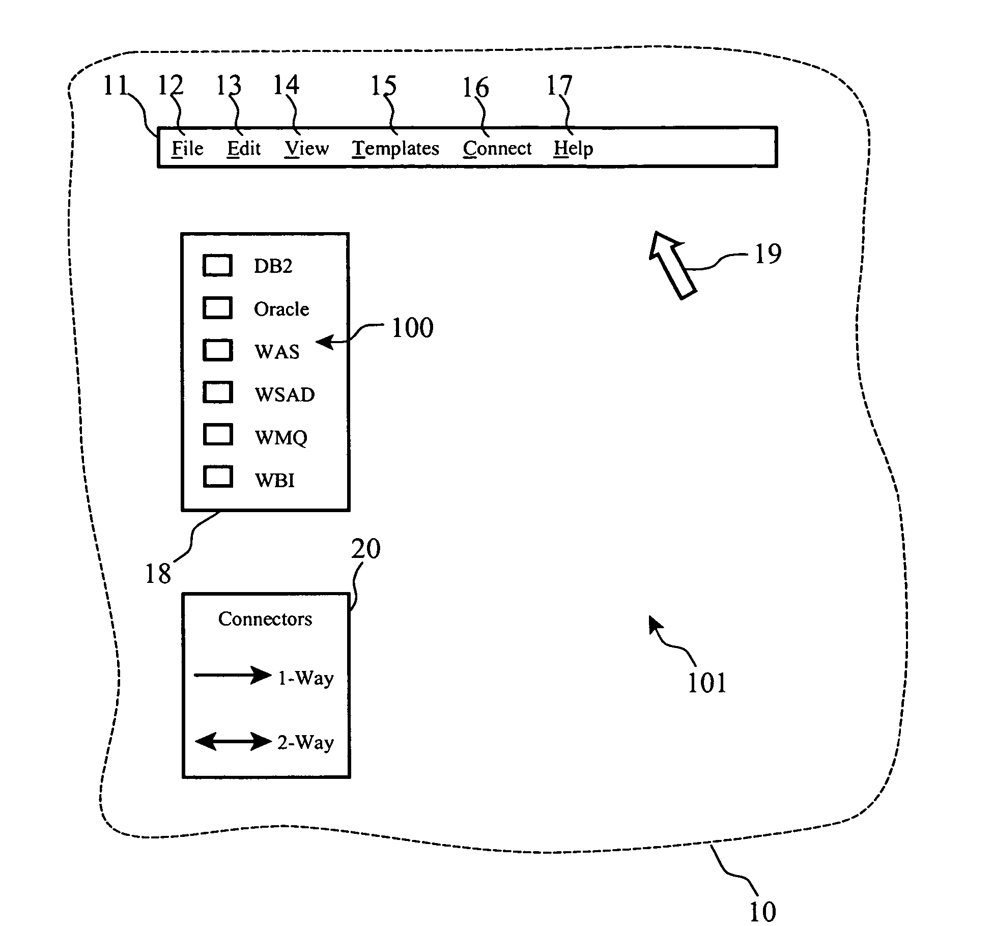
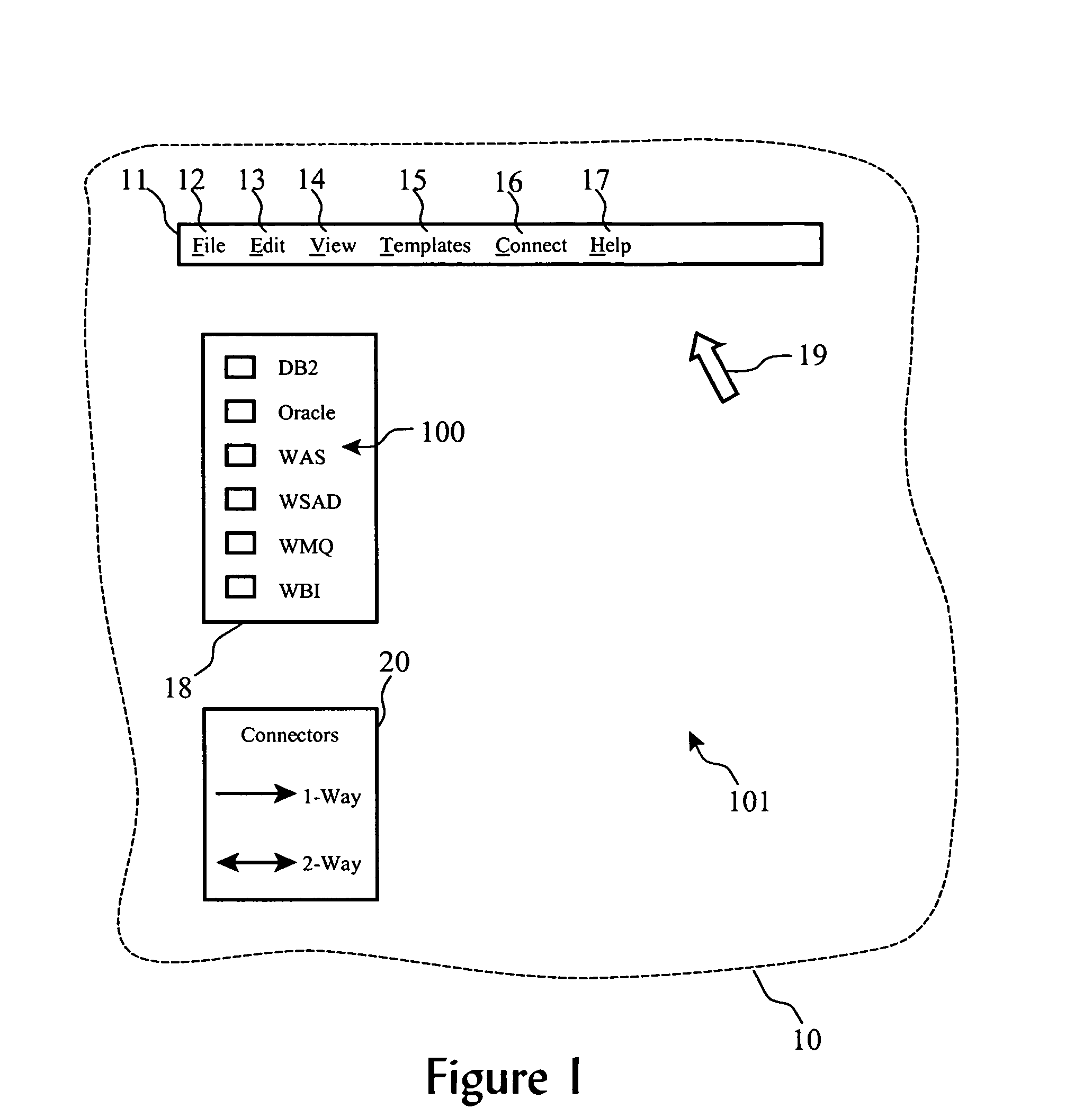
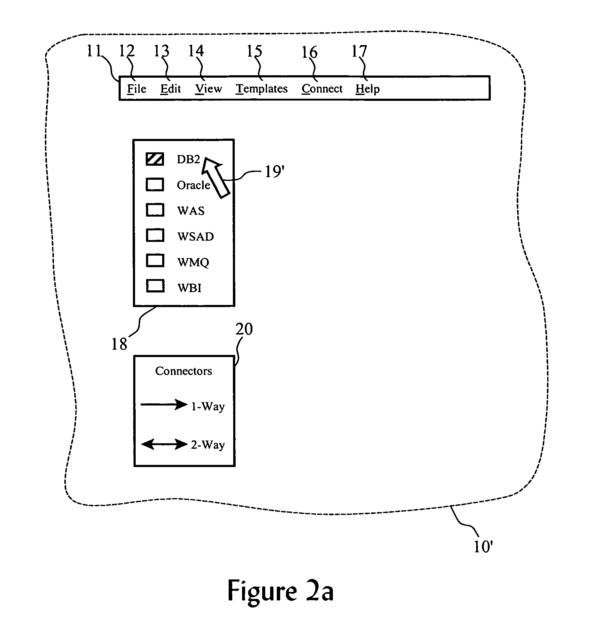
[0027] Our invention, referred to as the “Solution Builder Wizard”, uses a Graphical User Interface (“GUI”), a set of predefined “templates” for each component, and implementation intelligence logic, to enable speedy assembly of various solution components together into one cohesive solution. Each “template” coupled with the implementation logic for each combination of component interfaces defines a set of configuration options and parameters which can be used to customize the combination of components, without need of a high level of expertise in either component. Preferably, the templates incorporate the most common options and configurations employed, leaving out obscure or rarely used options to reduce confusion by the system developer. Default configuration parameters and values may aid in quickly defining interfaces between components so that the system developers must only change the parameters that need to be changed from default values.

[0028] Prototypes and proof of concep...


PUM

PropertyMeasurementUnit
interface parametersaaaaaaaaaa
areaaaaaaaaaaa
system solution behavioral modelaaaaaaaaaa

Abstract

A computing solution is defined by displaying to a user in a graphical user interface a palette of icons representing available computing system components for potential use in a computing solution, each of which has an associated partially-defined behavioral model. The partially-defined behavioral models contain configurable behavioral and interface parameters. When the user selects one or more of the computing system components on the palette, an instance of each selected component is created, placed, arranged and displayed in a design area. The user can then define connections between each instance of component in the design area, which triggers predetermined logical processes to prompt the user for inputs to complete the partially-defined models for each instance of component. Finally, system solution behavioral model is created or saved comprising a collection of configured component instance behavioral models.

Description

BACKGROUND OF THE INVENTION [0001] 1. Field of the Invention [0002] This invention relates to a Solution Builder Wizard that utilizes templates and interfaces with predefined intelligence to allow speedy assembly of various software components into one cohesive product form. [0003] 2. Background of the Invention [0004] Recently, a shift has occurred among enterprise computing supplies to address “vertical markets”. These “solutions” are targeted to the specific needs, business processes, and problems for a certain industry, such as insurance claim processing, health care insurance filing, mortgage application handling, etc. Industry solutions often consists of one or more operating systems and middleware products that are packaged along with customized, industry specific, data, and code that are installed and configured to function as one cohesive business solution. There are many software and consulting firms who are focused on implementing vertical industry solutions using a colle...

Claims


Application Information

Patent Timeline
Patent Type & Authority Applications(United States)
IPC IPC(8): G03C5/18
CPCG06F8/34
Inventor SANJAR, AMIR FARROKHULLMANN, CRISTI NESBITTWILLIAMSON, PAUL STUART
Owner IBM CORP
Why Eureka
Try Eureka