Circuit and method for reducing the size and cost of switch-mode power supplies

a switch-mode power supply and circuit technology, applied in the field of power supplies, can solve the problems of high number and cost of components, limited supply at an upper voltage, and generally more expensive than other regulated power supplies, and achieve the effect of reducing the size and cost of switch-mode power supplies

Active Publication Date: 2006-10-26
COMMSCOPE DSL SYST LLC
View PDF3 Cites 4 Cited by
  • Summary
  • Abstract
  • Description
  • Claims
  • Application Information

AI Technical Summary

Benefits of technology

[0009] The present invention provides an improved circuit and method for decreasing the size and cost of switch mode power supplies. In accordance with a preferred embodiment of the present invention, a feedback circuit for a switch mode power supply is provided that includes two error amplifiers. The input of a first error amplifier is coupled to the output voltage across the load of the supply, and the input of a second error amplifier is coupled to a voltage that is proportional to the output current drawn by the load of the supply. Each one of the error amplifiers includes an adjustable shunt regulator device that functions as a voltage reference, amplifier stage and open collector output transistor. Also, the outputs of the shunt regulators are connected together. Therefore, the shunt regulator of the first error amplifier can be used to select a voltage limit for the power supply, the shunt regulator of the second error amplifier can be used to select a current set point for the power supply, and the open collector output transistors of the shunt regulators OR the output signals from the two error amplifiers to produce a signal indicating the loading of the supply. In this manner, the present invention provides an improved feedback circuit for a switch mode power supply that performs the same functions as prior feedback circuits, but has at least three less discrete components (e.g., two diodes and a voltage reference) than the prior feedback circuits. Thus, the present invention significantly reduces both the size and cost of switch mode power supplies.

Problems solved by technology

Consequently, a voltage limit is placed on the supply, so that if the load opens up completely, the supply will be limited at an upper voltage.
Notwithstanding the distinct advantages of the existing power supply feedback signal technique that can be used in a switch mode power supply, a significant problem that still exists with such switch mode power supplies is that they are generally more expensive than other regulated power supplies (particularly at the lower power levels), because of the relatively high number and cost of components in the switch mode power supplies and relative complexity of the circuitry involved.
Consequently, the bulkier, less accurate, and more inefficient power supplies are often used in cost-sensitive applications.

Method used


Image

  • Circuit and method for reducing the size and cost of switch-mode power supplies
  • Circuit and method for reducing the size and cost of switch-mode power supplies
  • Circuit and method for reducing the size and cost of switch-mode power supplies

Examples


Embodiment Construction

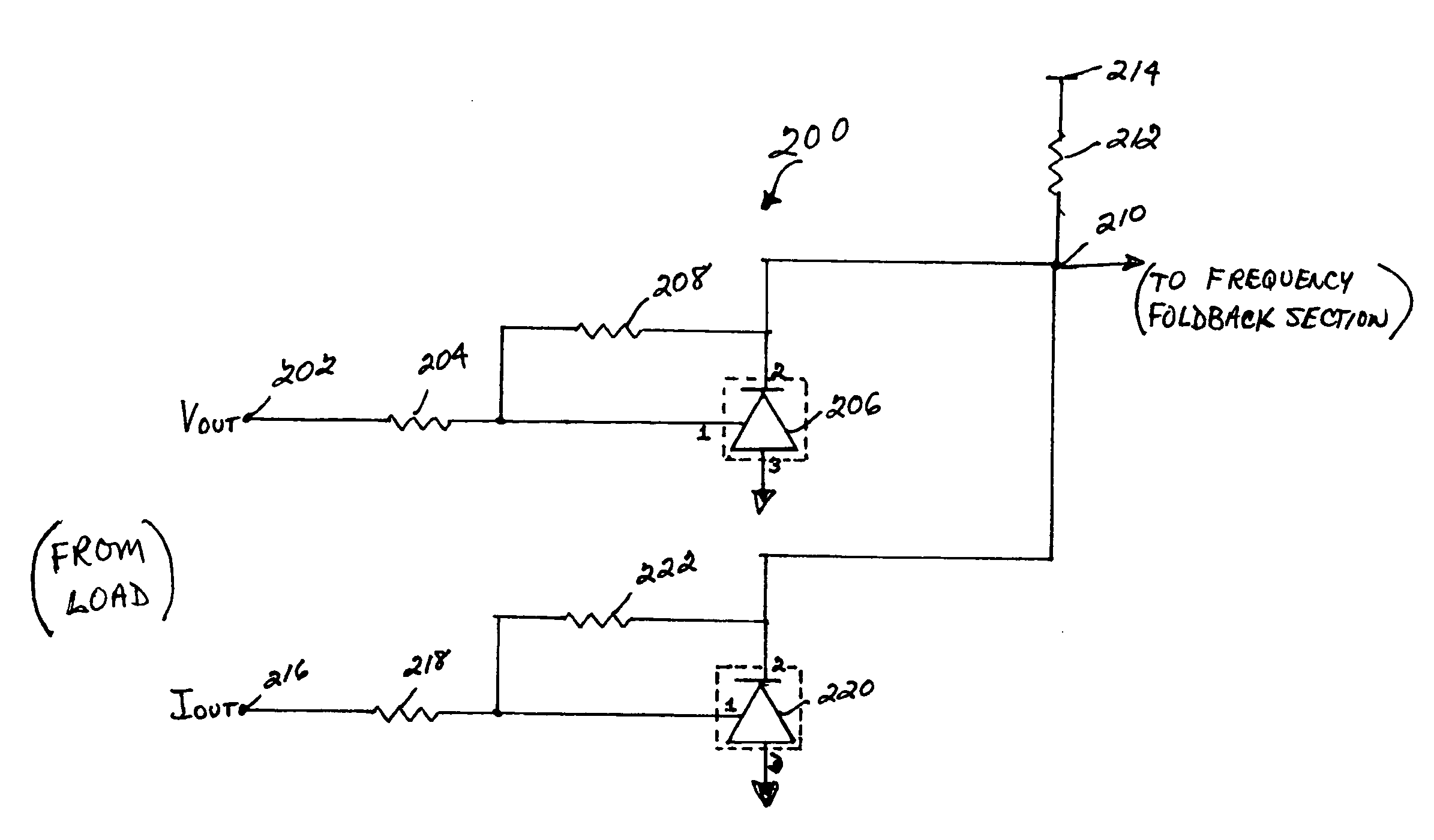
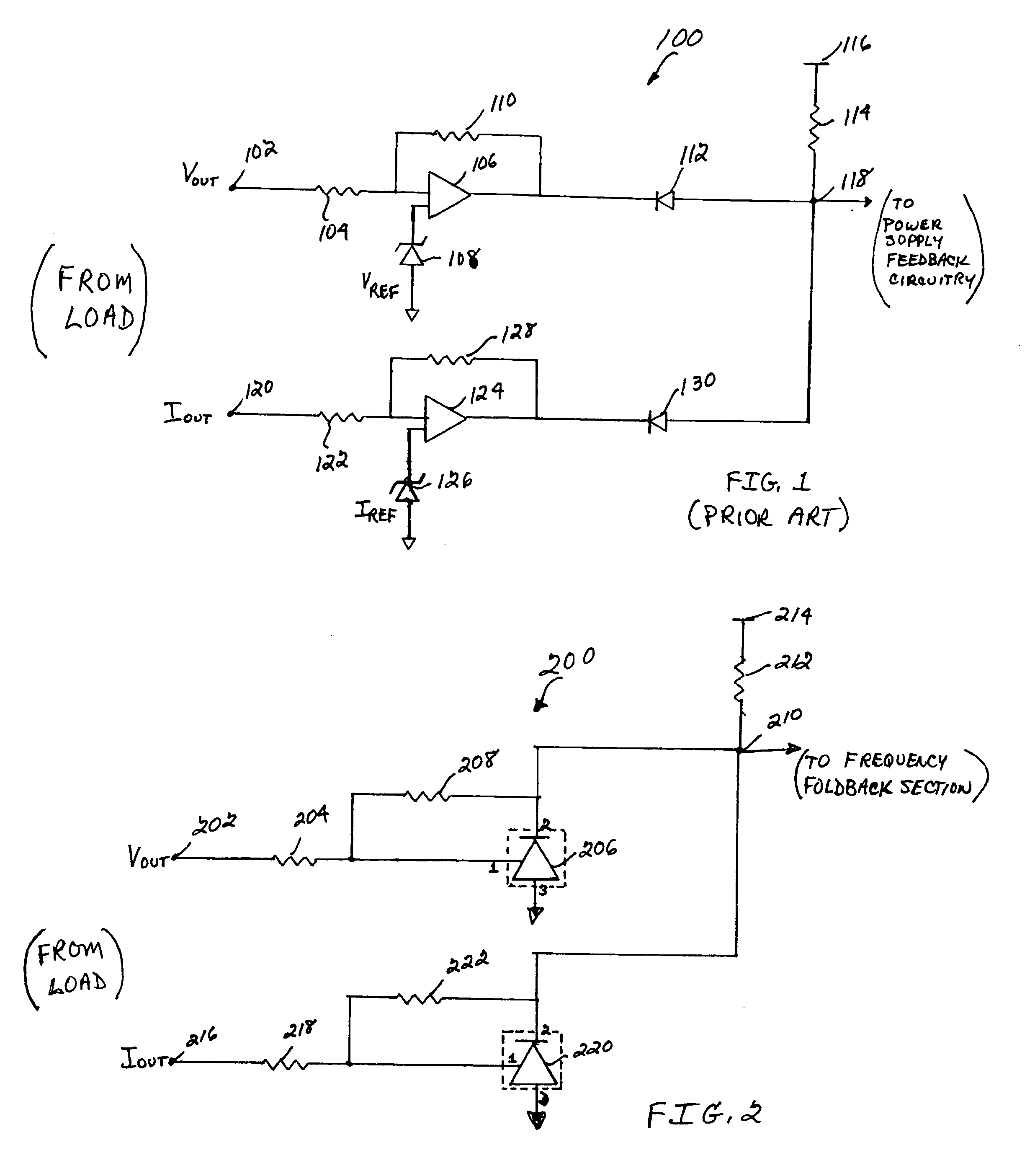
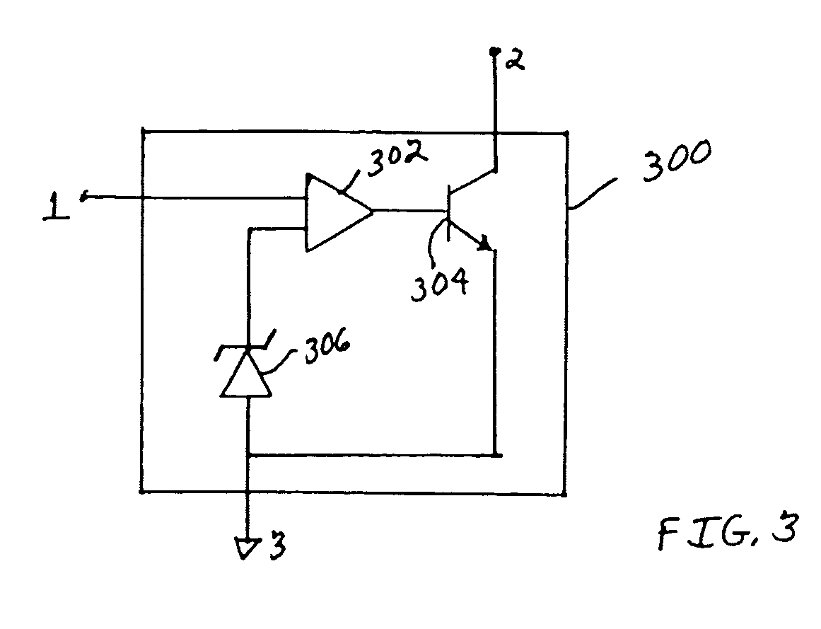
[0014] With reference now to the figures, FIG. 2 depicts an improved feedback circuit 200 for a switch mode power supply, which can be used to implement a preferred embodiment of the present invention. The compensation signal output from section 200 indicates the loading of the supply and can be used, for example, to perform duty cycle control operations for switch mode power supplies in high technology applications, such as for example, in Simplex Span Powered T1 power supply applications. As shown, feedback circuit 200 includes a first input connection 202, which is coupled to a voltage source (e.g., VOUT) across a power supply load (not shown). A (load) voltage sensed at connection 202 is developed across resistor 204 and applied to a first input terminal (1) of a shunt regulator device 206. For this embodiment, a detailed view of an example shunt regulator device that can be used to implement shunt regulator device 206, is shown in, and described below with respect to, FIG. 3.

[...


PUM


Abstract

An improved circuit and method for decreasing the size and cost of switch mode power supplies is disclosed. In one illustrative example, a feedback circuit for a switch mode power supply is disclosed that includes two error amplifiers. The input of a first error amplifier is coupled to a voltage source associated with a load for the supply, and the input of a second error amplifier is coupled to a current source also associated with the load for the supply. Each one of the error amplifiers includes an adjustable shunt regulator that functions as an amplifier stage and diode. Also, the outputs of the. shunt regulators are connected together. Therefore, the shunt regulator of the first error amplifier can be used to select a voltage limit for the power supply, the shunt regulator of the second error amplifier can be used to select a current set point for the power supply, and the open collector functions of the shunt regulators serve to OR the output signals from the two error amplifiers to produce a signal indicating the loading of the supply. In this manner, an improved feedback circuit for a switch mode power supply is provided that performs the same functions as prior feedback circuits, but has at least three less discrete components (e.g., two diodes and a voltage reference) than the prior feedback circuits. Thus, the disclosed feedback circuit significantly reduces both the size and cost of switch mode power supplies.

Description

RELATED APPLICATIONS [0001] The present application is related to commonly assigned and co-pending U.S. patent application Ser. No. ______ (Attorney Docket No. 100.697US01) entitled “CIRCUIT AND METHOD FOR INCREASING THE STABILITY OF SWITCH MODE POWER SUPPLIES,” filed on the same date as the present application, which is incorporated herein by reference in its entirety.FIELD OF THE INVENTION [0002] The present invention relates generally to the power supply field, and more specifically, but not exclusively, to a circuit and method for reducing the number of components, and the size and cost of switch mode power supplies. BACKGROUND OF THE INVENTION [0003] Switch mode power supplies are used in a broad range of electronic applications, such as, for example, telecommunication systems, computers, television equipment, video equipment, etc., where it is important to accurately regulate a power supply output over a wide range of loads. A significant advantage of switch mode power supplie...

Claims


Application Information

Patent Timeline
Patent Type & Authority Applications(United States)
IPC IPC(8): H02M7/00
CPCH02M3/156G05F3/18
Inventor CARTER, MICHAEL
Owner COMMSCOPE DSL SYST LLC
Why Eureka
Try Eureka