

Electronic device including first and second parts and a flexible printed circuit board for electrically connecting the two
- Summary
- Abstract
- Description
- Claims
- Application Information
AI Technical Summary
Benefits of technology
Problems solved by technology
Method used
Image

Examples
Embodiment Construction
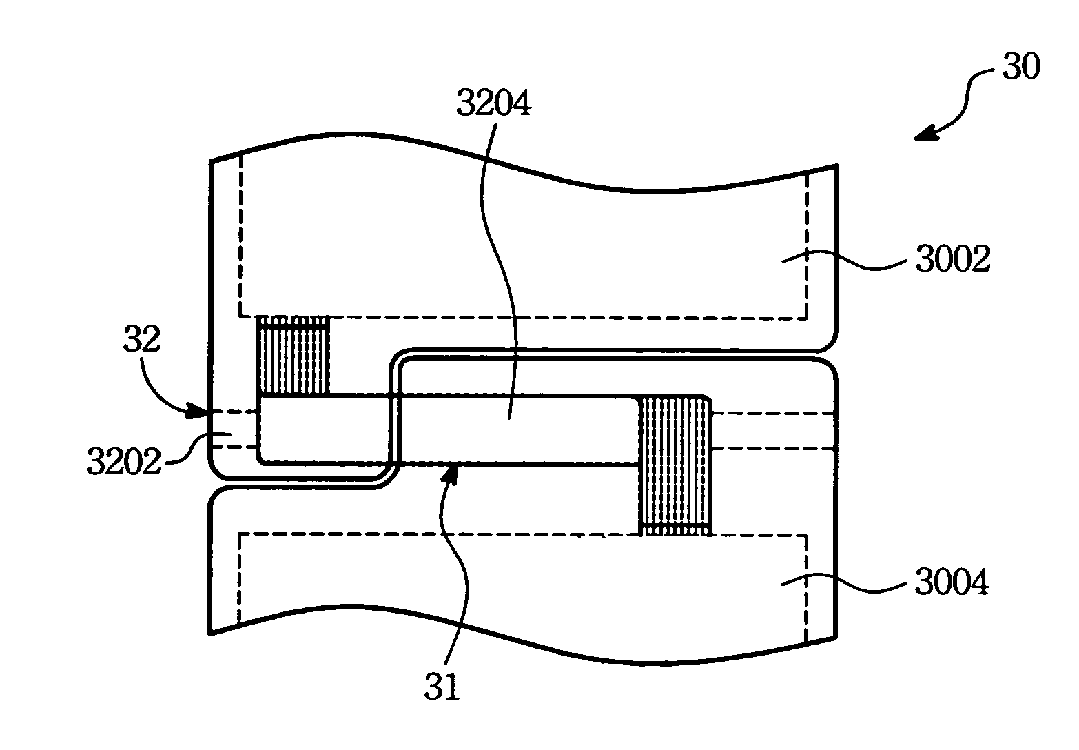
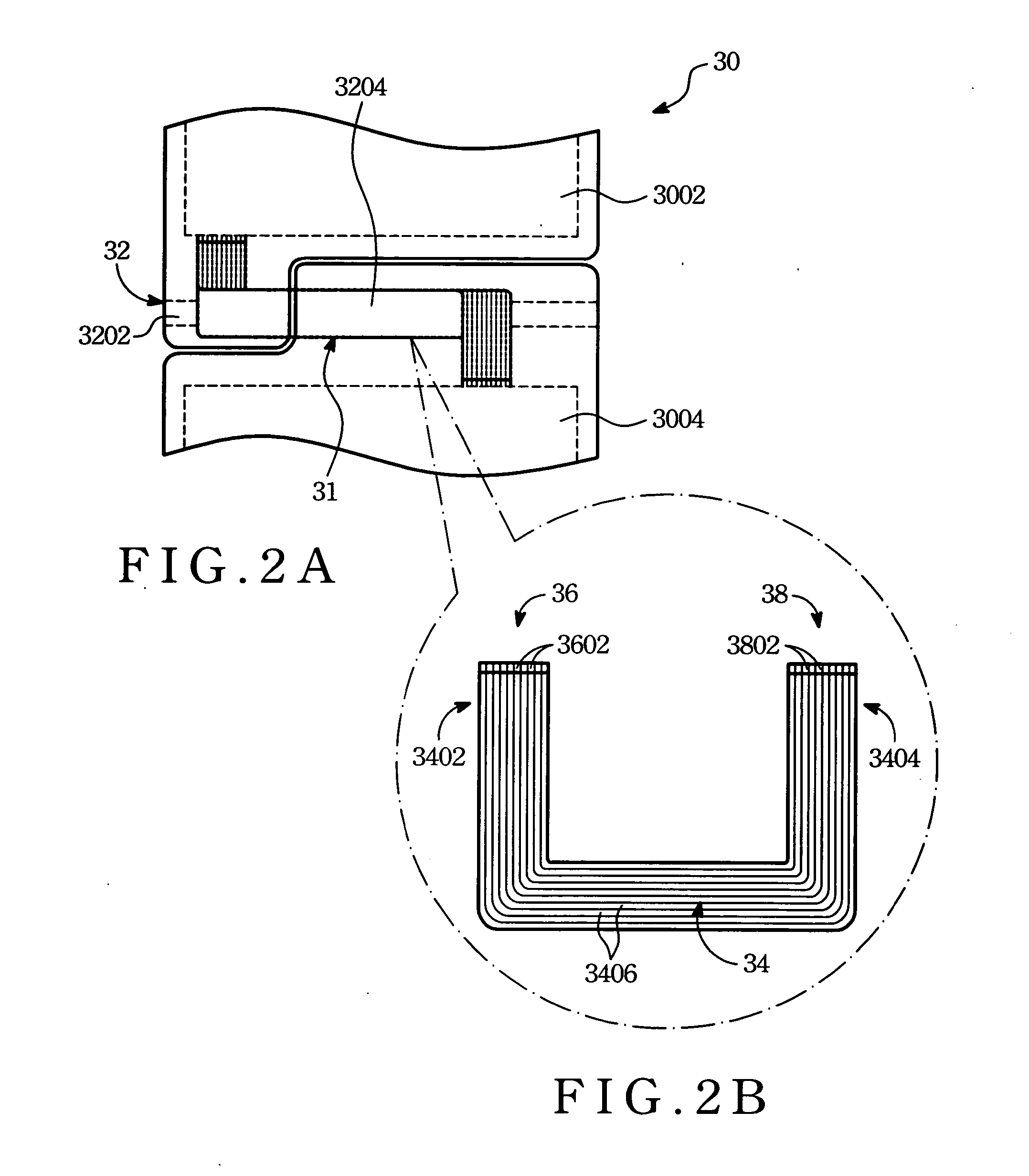
[0014] Referring to FIGS. 2A and 2B, the preferred embodiment of an electronic device 30 (such as a mobile phone or a flip phone) according to the present invention is shown to include a first part 3004, a second part 3002, a coupler shaft 32, and a flexible printed circuit board 34 (also known as flexible connector).
[0015] The coupler shaft 32 is disposed between the first part 3004 (hereinafter a main body) and the second part 3002 (hereinafter a cover member) for pivotally coupling the first and second parts 3002, 3004 in such a manner that the main body 3004 and the cover member 3002 are disposed at two opposite sides of the coupler shaft 32 (see FIG. 2A). The main body 3004 and the cover member 3002 are movable relative to each other about the coupler shaft 32. The structure of the coupler shaft 32 will be described in greater detail later.
[0016] The main body 3004 generally includes a keypad (not visible) for data inputting and an antenna assembly (not visible) for transmitt...
PUM
 Abstract
Description
Claims
Application Information