Sliding cover for slot of electronic device

a technology of electronic devices and sliding covers, which is applied in the direction of electrical apparatus casings/cabinets/drawers, details of portable computers, instruments, etc., can solve the problems of reducing the useful life of connections, reducing the useful life of connections, and increasing manufacturing costs, so as to reduce the useful life and reduce manufacturing costs. , the effect of reducing the useful li

Inactive Publication Date: 2007-01-25
INVENTEC CORP
View PDF9 Cites 15 Cited by
  • Summary
  • Abstract
  • Description
  • Claims
  • Application Information

AI Technical Summary

Benefits of technology

[0009] After understanding the needs of the market and vast users and considerable research and experimentation, a sliding cover for slot of electronic device according to the present invention has been devised by the present inventor so as to overcome the above drawbacks of the prior art, i.e., in one design the ports and the slot of the case are exposed on a front panel thereof, however, this cannot prevent dust, foreign objects, etc. from entering the case and thus the useful life is shortened, in another design an additional protection member is formed on the ports and the slot, and however, the protection member not only increases the manufacturing cost but also complicates the construction.
[0010] It is an object of the present invention to provide an electronic device comprising a case including one or more connections disposed on a front panel thereof, a transverse groove disposed along the front panel of the case and above one of the connections, and a transverse rail disposed on the front panel of the case and below one of the connections; and a sliding cover including a plurality of latches disposed on a top edge thereof, and a slide disposed on a bottom edge thereof, the slide extended toward the connections, wherein the latches are slidably secured to the groove, the slide is adapted to slidably receive the rail for completing an assembly of the sliding cover, and the sliding cover is adapted to transversely slide along the groove for covering the opening of one of the connections or not. By utilizing this sliding cover, not only the useful life of the connections (e.g., slot and ports) is prolonged but also drawbacks of the connections of the prior electronic device (e.g., notebook) are eliminated. The drawbacks include the ports and the slot on the case of the electronic device being exposed on a front panel thereof, dust, foreign objects, etc entered the case, and thus the useful life of the connections being shortened.
[0011] In one aspect of the present invention there are further provided a protuberance disposed on the front panel of the case proximate the connections and spaced from one side of one of the connections, two spaced projections disposed on the sliding cover facing the protuberance, either projection being adapted to lockingly engage the protuberance when the sliding cover is disposed either in a first position to cover the slot or in a second position to expose the slot by sliding, and a protrusion disposed under either latch, and wherein the protrusions are adapted to cooperate with the projections such that a structural strength of the sliding cover can be enhanced, and the projection and the protrusion are adapted to facilitate grasping and sliding of the sliding cover by the hand.

Problems solved by technology

After understanding the needs of the market and vast users and considerable research and experimentation, a sliding cover for slot of electronic device according to the present invention has been devised by the present inventor so as to overcome the above drawbacks of the prior art, i.e., in one design the ports and the slot of the case are exposed on a front panel thereof, however, this cannot prevent dust, foreign objects, etc. from entering the case and thus the useful life is shortened, in another design an additional protection member is formed on the ports and the slot, and however, the protection member not only increases the manufacturing cost but also complicates the construction.
The drawbacks include the ports and the slot on the case of the electronic device being exposed on a front panel thereof, dust, foreign objects, etc entered the case, and thus the useful life of the connections being shortened.

Method used


Image

  • Sliding cover for slot of electronic device
  • Sliding cover for slot of electronic device
  • Sliding cover for slot of electronic device

Examples


Embodiment Construction

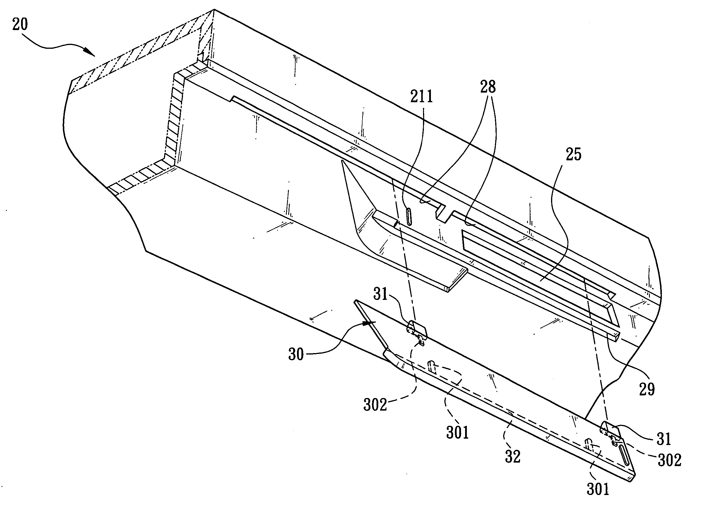
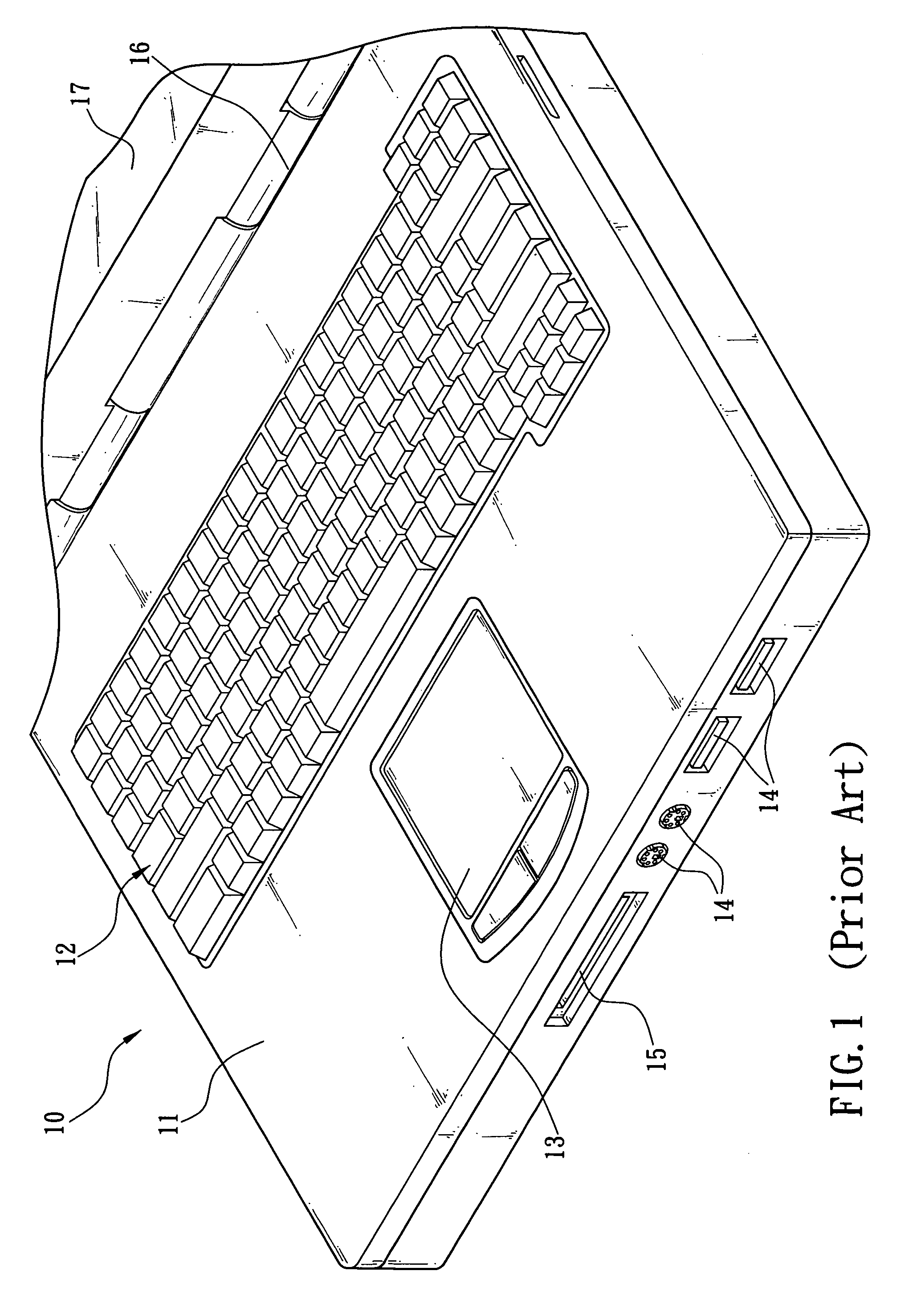
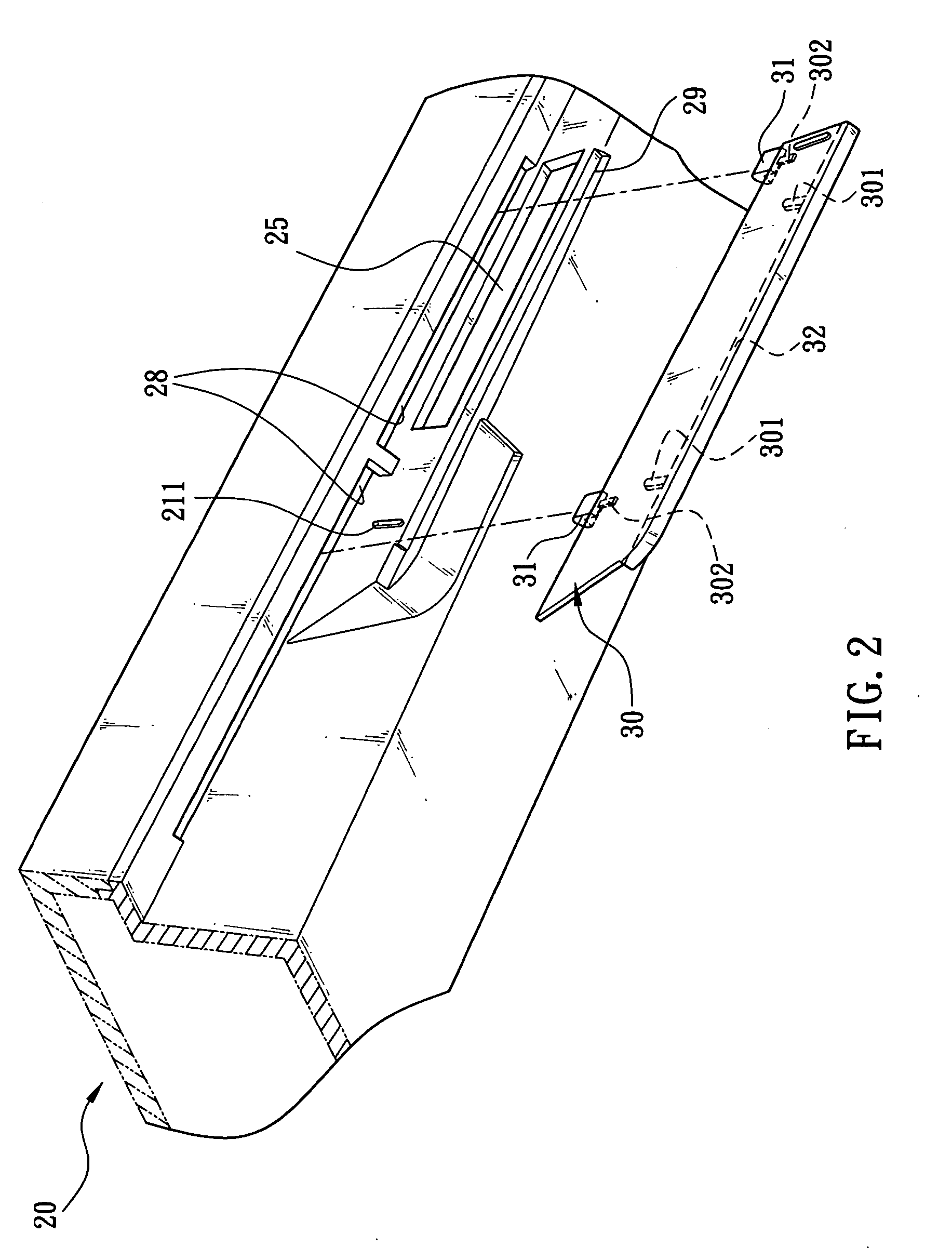
[0016] Referring to FIGS. 2 and 3, a preferred embodiment of the invention is shown. The preferred embodiment comprises an electronic device 20 and a sliding cover 30. In the embodiment the electronic device 20 is a notebook. The notebook 20 comprises a parallelepiped case 21 hingedly connected to a display 27 by a hinge 26 (see FIG. 3). Thus, the display 27 is adapted to pivot to either rest upon the case 21 for closing the notebook 20 or dispose away from the case 21 for opening the notebook 20 for operating. A keyboard 22 is provided on a top surface of the case 21 such that a user may enter data through the keyboard 22. A touch pad 23 is provided on the top surface of the case 21 below the keyboard 22, the touch pad 23 served to replace a typical mouse. A plurality of connections are provided on a front panel of the case 21. The connections are implemented as at least one port 24 (four are shown) and at least one slot 25 (one is shown). Each port 24 is implemented as a USB (univ...


PUM


Abstract

The present invention is to provide an electronic device comprising a case including one or more connections disposed on a front panel thereof, a transverse groove disposed along the front panel and above one of the connections, and a transverse rail disposed on the front panel and below one of the connections; and a sliding cover including a plurality of latches disposed on a top edge thereof, and a slide disposed on a bottom edge thereof and extended toward the connections, wherein the latches are slidably secured to the groove, the slide is adapted to slidably receive the rail for completing an assembly of the sliding cover, and the sliding cover is adapted to transversely slide along the groove for covering one of the connections or not.

Description

FIELD OF THE INVENTION [0001] The present invention relates to a protection device of an electronic device and more particularly to such an electronic device having connections being protected by a sliding cover so as to protect the connections from being polluted by dust and foreign objects and prolong the useful life thereof. BACKGROUND OF THE INVENTION [0002] A wide variety of portable digital devices (e.g., notebooks, PDAs (personal digital assistants), etc.) are commercially available in a fast pace in recent years as network and communication technologies advance. Moreover, such digital devices are inexpensive, compact, and easy to carry. They not only fulfill the needs of people in wireless communication in our daily life and work but also fulfill the needs of people in entertainment and data processing. For example, a variety of video games and database software packages are commercially available. Thus, people have more changes to use the portable devices. Particularly, in ...

Claims


Application Information

Patent Timeline
Patent Type & Authority Applications(United States)
IPC IPC(8): H05K7/00
CPCG06F1/1616H05K5/03G06F1/1656
Inventor DU, YU-JEN
Owner INVENTEC CORP
Why Eureka
Try Eureka