Method and apparatus for real time identification and correction of pixel defects for image sensor arrays

a technology of image sensor array and real-time identification, applied in image enhancement, color signal processing circuit, instruments, etc., can solve the problems of limited number of defects that can be corrected, the effect of affecting a significant portion of the image is compounded, and the defect location is required. , to achieve the effect of reducing peak-to-peak noise variations in the imag

a technology of image sensor array and real-time identification, applied in image enhancement, color signal processing circuit, instruments, etc., can solve the problems of limited number of defects that can be corrected, the effect of affecting a significant portion of the image is compounded, and the defect location is required. , to achieve the effect of reducing peak-to-peak noise variations in the imag

US20070058056A1Active Publication Date: 2007-03-15APTINA IMAGING CORP

Image

  • Method and apparatus for real time identification and correction of pixel defects for image sensor arrays
  • Method and apparatus for real time identification and correction of pixel defects for image sensor arrays
  • Method and apparatus for real time identification and correction of pixel defects for image sensor arrays

Examples


Embodiment Construction

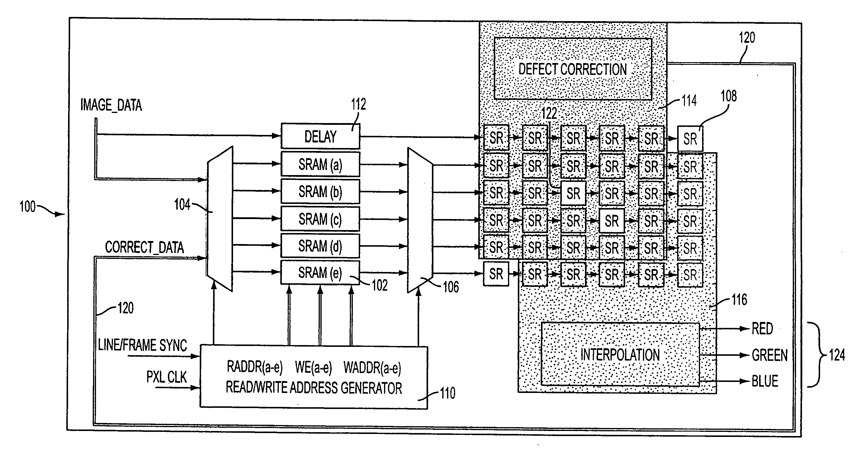
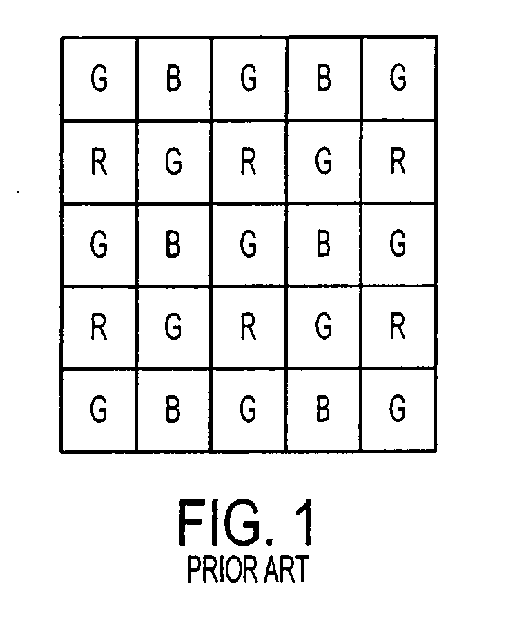
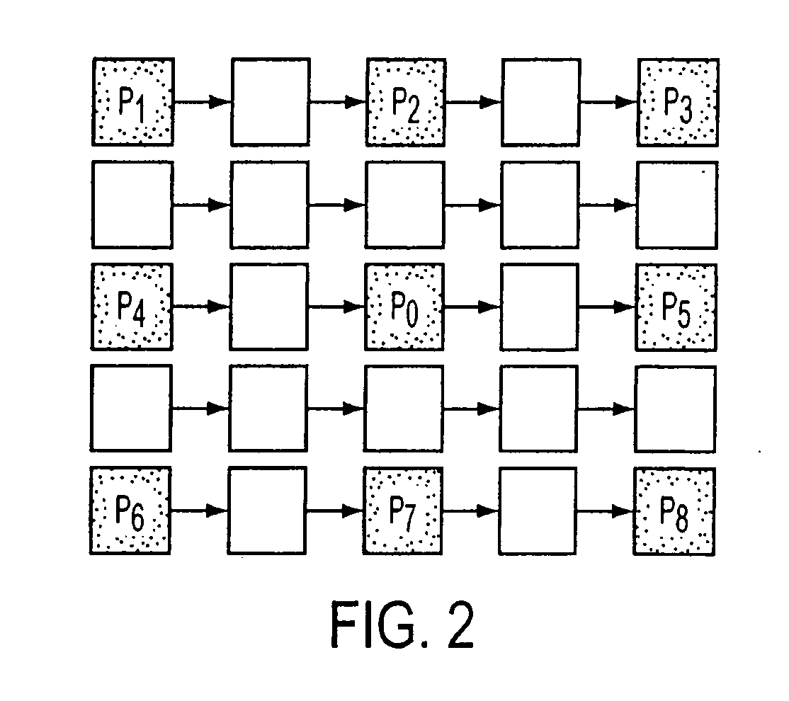
[0019] In the method aspect of the present invention, the signal value of each pixel in an image obtained by an image sensor is compared with the values for at least eight closest surrounding pixels having the same color filter located adjacent to or near the pixel being tested. An example of this method will be described for an image obtained by an image sensor having a Bayer mosaic filter array. As illustrated in FIG. 2, the signal value of the central pixel, P0, is compared with the signal values for each of the eight closest surrounding pixels of the same color. In this example, these eight closest surrounding pixels are located along the same row (P4, P5), column (P2, P7), and diagonally (P1, P3, P6, and P8) from the pixel being tested (P0), each spaced one pixel away from P0 in the relevant direction.

[0020] If the signal of P0 is larger than the respective signals of all eight surrounding pixels P1 through P8, then the signal value for P0 is substituted with the maximum signa...


PUM


Abstract

An image processing system and method compares each pixel of an image obtained from an image sensor array with at least eight surrounding pixels of the same color in the filter array. If the signal of a given pixel is larger than the respective signals of all eight surrounding pixels of the same color, then the value of that central pixel signal is substituted with the maximum signal value among the surrounding eight pixels of the same color. Similarly, if the signal of a given pixel is smaller than the respective signals of all eight surrounding pixels of the same color, then the value of that central pixel signal is substituted with the minimum signal value among the surrounding eight pixels of the same color.

Description

FIELD OF THE INVENTION [0001] The present invention relates to a method and apparatus that enables real time identification and correction of defective pixels in an image sensor array in a digital imaging environment. BACKGROUND OF THE INVENTION [0002] When an image is exposed onto an image sensor, each pixel records the amount of light that it “sees” as an intensity level between a dark signal wherein no light reaches that pixel, to a full white signal representing the maximum amount of light detectable by that pixel. The image thus captured by the image sensor is processed as a grayscale image. [0003] To detect the colors of the image exposed onto the image sensor, the pixels of the image sensor are covered with a respective color filter that absorbs light wavelengths for all colors except the color of the filter. An exemplary method for acquiring color information from an image sensor is to place a color filter array over the pixels of an image sensor. The most common example of ...

Claims


Application Information

Patent Timeline
15 Mar 2007
Publication
US20070058056A1
IPC
H04N9/04; H04N23/12; H04N25/00
CPC
H04N5/3675; G06T5/20; G06T5/005; H04N25/683; G06T5/77
Inventors
KAPLINSKY, MICHAEL; SUBBOTIN, IGOR