Exhaust assembly for mass ejection drive system

a technology of exhaust assembly and drive system, which is applied in the direction of rocket engine plants, machines/engines, instruments, etc., can solve the problems of affecting the accuracy of target calculations, and affecting the effect of mass ejection

Inactive Publication Date: 2007-07-05
RAYTHEON CO
View PDF8 Cites 12 Cited by
  • Summary
  • Abstract
  • Description
  • Claims
  • Application Information

AI Technical Summary

Benefits of technology

[0006] In various representative aspects, the present invention corresponds to a system and method for providing an exhaust assembly for a mass ejection drive system adapted to address the deficiencies associated with the conventional art. Exemplary features generally include: a selectively engaged vane, a selectively deployed tailfin, and a shaft coupling such a vane to such a tailfin.

Problems solved by technology

This poses a number of problems for drive systems configured for use with launch tubes.
For mass ejection drive systems configured for deployment from a launch tube, the duration of mass ejection is likely to exceed the time that it takes for the device to exit the launch tube.
Additionally, because the duration of mass ejection is likely to exceed the time that it takes to exit the launch tube, maximum rotation will generally not be achieved upon exit from the launch tube, but at some subsequent point in time.
These issues may operate to complicate targeting calculations and reduce predictability of the drive system with respect to targeting.
However, problems with ablative vanes include irregular and unpredictable erosion of the vanes.
Moreover, for drive systems configured for deployment from a launch tube, ablative vanes have a tendency to foul the launch tube by virtue of their substantially direct contact with launch tube surfaces.

Method used


Image

  • Exhaust assembly for mass ejection drive system
  • Exhaust assembly for mass ejection drive system
  • Exhaust assembly for mass ejection drive system

Examples


Embodiment Construction

[0017] The following representative descriptions of the present invention generally relate to exemplary embodiments and the inventors' conception of the best mode, and are not intended to limit the scope, applicability or configuration of the invention in any way. Rather, the following description is intended to provide convenient illustrations for implementing various embodiments of the invention. As will become apparent, changes may be made in the operation and / or arrangement of any of the elements described in the disclosed exemplary embodiments without departing from the spirit and scope of the invention.

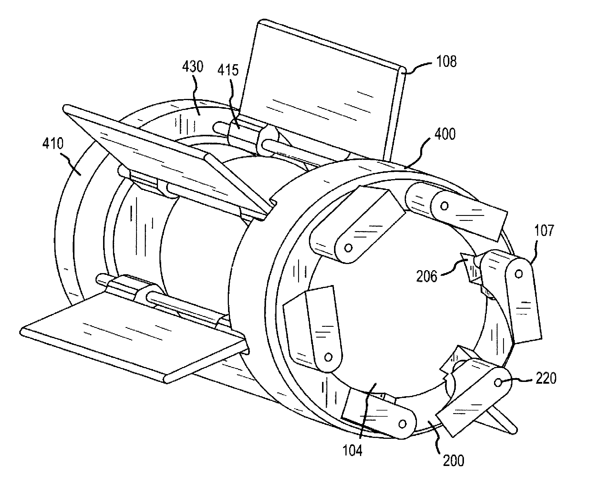
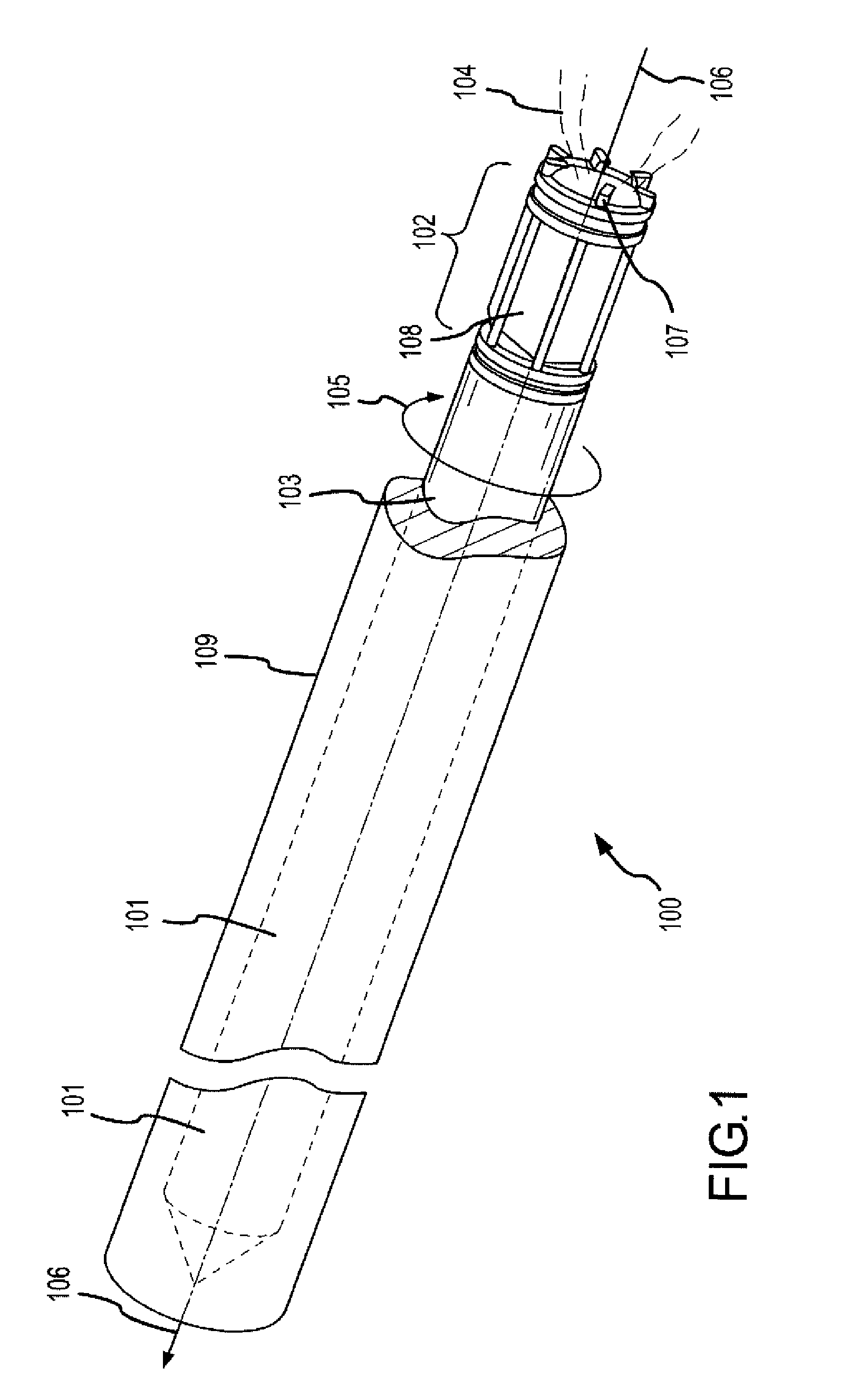
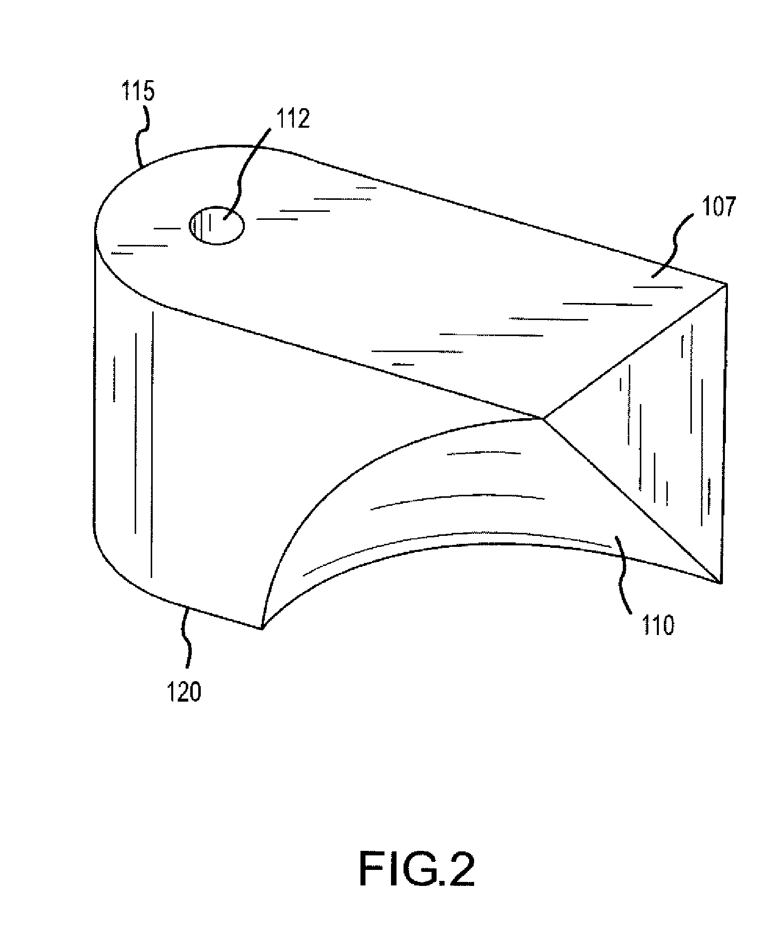
[0018] Various representative implementations of the present invention may be applied to any exhaust assembly for affecting torque about the principal axis of a mass ejection drive system. Certain representative implementations may include, for example: an exhaust assembly for affecting torque about the principal axis of a missile, which may include, for example: a rocket; a se...


PUM


Abstract

The present invention discloses a system, device and method for providing an exhaust assembly adapted for use with a mass ejection drive system to produce rotational torque about the principle axis of the drive system. Representative features generally include a vane suitably configured to at least partially engage a mass ejecta stream to apply a net rotational torque about the principal axis of the drive system, and a tailfin coupled to the at least one vane. The tailfin is configured to selectively deploy from an at least partially stowed position in order to decrease the application of net rotational torque about the principal axis of the drive system.

Description

RELATED APPLICATIONS [0001] This application claims priority to U.S. Provisional Patent Application Ser. No. 60 / 727,135 entitled “Integrated Tail Fin and Torque [Imparting] Rocket” filed in the United States Patent and Trademark Office on Oct. 13, 2005 by Edgar Melkers.FIELD OF INVENTION [0002] The present invention generally concerns mass ejection drive systems, and more particularly, representative and exemplary embodiments of the present invention generally relate to systems and methods for providing exhaust assemblies adapted for affecting torque about the deployment axis of a rocket or missile. BACKGROUND OF INVENTION [0003] To improve the performance of mass ejection drive systems, it is sometimes desirable to rotate the drive system about its principal axis. Conventional structures for producing rotation include fluted nozzles and ablative vanes. [0004] Fluted nozzles are generally fixed structures that are at least partially disposed within the ejecta stream of the mass ejec...

Claims


Application Information

Patent Timeline
Patent Type & Authority Applications(United States)
IPC IPC(8): F42B10/14F42B15/01
CPCF02K1/78F02K9/97F05D2250/31F42B10/28F42B10/665F42B10/16
Inventor MELKERS, EDGAR R.EISENTRAUT, RUDYSTRASSMAN, DORON
Owner RAYTHEON CO
Why Eureka
Try Eureka