Token passing protocol for RFID systems

Active Publication Date: 2007-10-04
SYMBOL TECH LLC
View PDF7 Cites 21 Cited by
  • Summary
  • Abstract
  • Description
  • Claims
  • Application Information

AI Technical Summary

Benefits of technology

[0010] Methods, systems, and devices for operation of RFID readers in a networked configuration are described. The n

Problems solved by technology

However, when multiple readers simultaneously send out interrogation signals to an overlapping group of tags, this may cause interference between the interrogation signals.
As a result, there may be signal conflict and/or signal

Method used


Image

  • Token passing protocol for RFID systems
  • Token passing protocol for RFID systems
  • Token passing protocol for RFID systems

Examples


example reader operational embodiments

[0051]FIG. 3A shows an example token passing ring topology. A token passing network 350 includes readers 352a-352f arranged in a ring with links 354a-354f coupling readers in the ring. Each of readers 352a-352f accesses a communication medium when in possession of a token, and then passes the token on to the next reader via links 354a-354f. For instance, after accessing the communications medium (e.g. by interrogating a tag), reader 352a passes the token to reader 352b via link 354a.

[0052]FIG. 3B shows a flowchart 300 providing steps for example communications in a reader network, according to the present invention. Flowchart 300 relates to an example token passing protocol. The steps of flowchart 300 can be performed by embodiments of readers described herein. Other structural and operational embodiments will be apparent to persons skilled in the relevant art(s) based on the following discussion related to flowchart 300. The steps shown in FIG. 3B do not necessarily have to occur ...

example apparatus embodiments

[0098] Embodiments of the present invention improve upon existing inter-reader signaling approaches, to better optimize usage of the RF communications medium for improved efficiency of reader to tag communications.

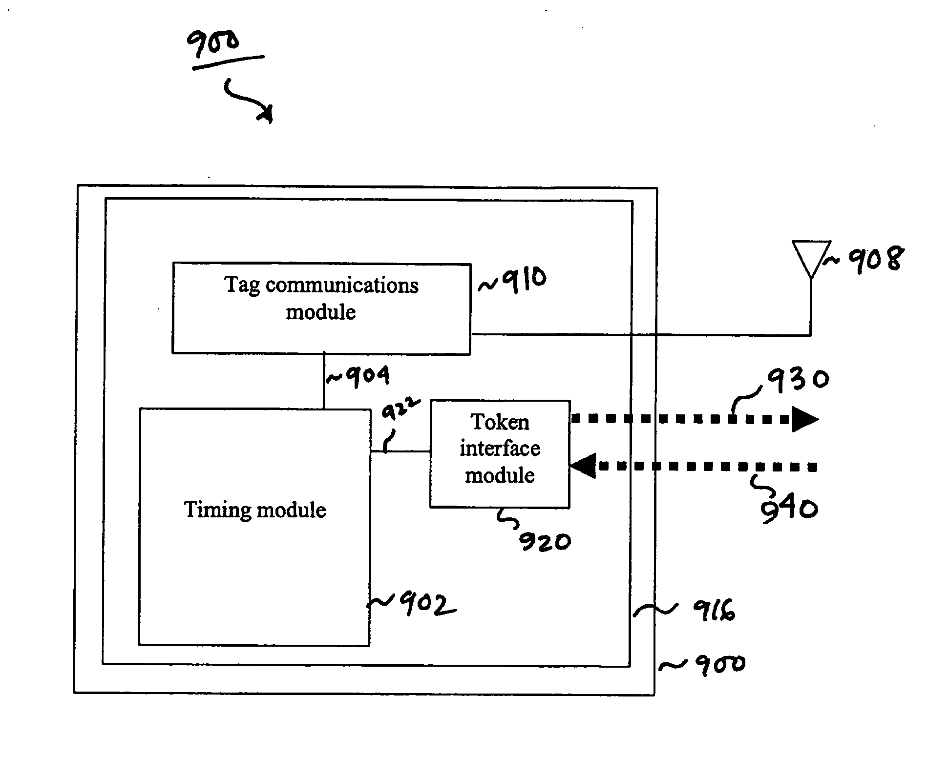
[0099] For example, FIG. 9 shows a reader 900 according to an embodiment of the present invention. Reader 900 has at least one antenna 908, and a controller unit 916 that includes various functional modules, including a tag communications module 910 coupled to the at least one antenna 908, a token interface module 920, and a timing module 902 coupled to tag communications module 910.

[0100] Token interface module 920 is configured to receive a token signal from another reader through link 940, and transmit a token signal to another reader through link 930. In an embodiment, links 930 and 940 may be wired links capable of transmitting signals with minimal latency.

[0101] Timing module 902 monitors communications performed by tag communications module 910. For example, timi...


PUM


Abstract

Methods, systems and apparatuses for RFID readers forming a reader network are described. In an aspect of the present invention, a plurality of RFID readers are configured to interrogate tags. Furthermore, the readers are configured to communicate with one another by transferring a token, represented by a signal. Possession of the token enables the reader to access a RF communications medium. Readers can be arranged in a ring configuration, and interconnected via wired links. A secondary token may circulate in the ring in addition to the primary token, to ensure redundancy in the system. A reader waits for a predetermined time interval before accessing the RF communications medium.

Description

BACKGROUND OF THE INVENTION [0001] 1. Field of the Invention [0002] The present invention relates generally to radio frequency identification (RFID) systems, and more particularly to systems and methods for communications among networked RFID readers to achieve efficient tag interrogations. [0003] 2. Background Art [0004] Radio frequency identification (RFID) tags are electronic devices that may be affixed to items whose presence is to be detected and / or monitored. [0005] The presence of an RFID tag, and therefore the presence of the item to which the tag is affixed, may be checked and monitored by devices known as “readers.” Readers typically have one or more antennas transmitting radio frequency signals to which tags respond. Once a reader receives signals back from the tags, the reader passes that information in digital form to a host computer, which decodes and processes the information. [0006] With the maturation of RFID technology, efficient communication between tags and read...

Claims


Application Information

Patent Timeline
IPC IPC(8): H04Q5/22
CPCH04W74/00
Inventor SOLEIMANI, MOHAMMADMOLINA, VICTOR HUGOSTRZELCZYK, MARTINDURON, MARKBOSCHINI, RONARNOLD, JENSPINSON, DARREL
Owner SYMBOL TECH LLC
Why Eureka
Try Eureka