Chain-chopping current mirror and method for stabilizing output currents

Active Publication Date: 2007-10-18
SILICON TOUCH TECH INC
View PDF4 Cites 1 Cited by
  • Summary
  • Abstract
  • Description
  • Claims
  • Application Information

AI Technical Summary

Benefits of technology

[0021]Since all the current channels are connected in series to each other through the switches and multiple series switching operations are conducted in the prese

Problems solved by technology

However, due to an imperfect IC (integrated circuit) process, a deviation between the real

Method used


Image

  • Chain-chopping current mirror and method for stabilizing output currents
  • Chain-chopping current mirror and method for stabilizing output currents
  • Chain-chopping current mirror and method for stabilizing output currents

Examples


Embodiment Construction

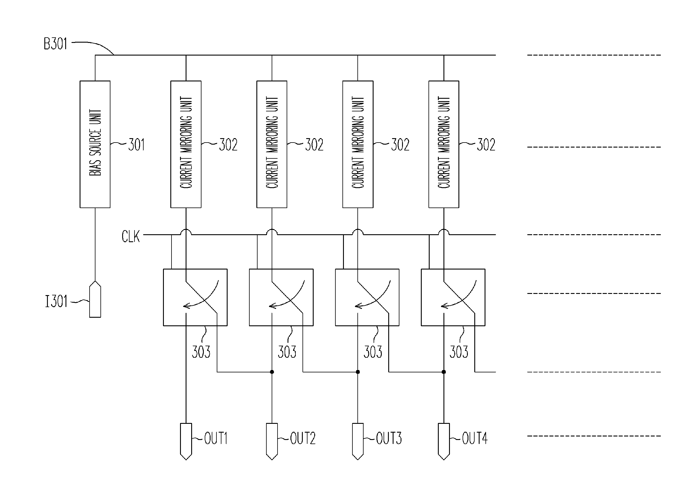
[0036]FIG. 3 is a block diagram of a chain-chopping current mirror circuit according to an embodiment of the present invention. Referring to FIG. 3, the current mirror includes a bias source unit 301, multiple current mirroring units 302, multiple switch components 303 and multiple output nodes OUT1˜OUTN.

[0037]The bias source unit 301 provides a reference bias B301 at a reference voltage terminal R301 according to the received current at an input terminal I301. Each current mirroring unit 302 includes a bias input terminal and an output terminal and the bias input terminal is coupled with the reference voltage terminal R301 to receive the reference bias B301. The output terminal of the current mirroring unit 302 outputs an output current according to the reference bias B301. Each switch component 303 includes a first terminal, a second terminal, a third terminal and a control terminal. The control terminal receives a clock signal, which decides whether the first terminal of the swit...


PUM


Abstract

A chain-chopping current mirror and a method for stabilizing output currents are disclosed. The current mirror includes multiple output nodes, a bias source unit, multiple current mirroring units and multiple switch components. The bias source unit provides a reference bias according to the received current. Each of the current mirroring units outputs an output current according to the reference bias. The control terminal of each the switch component receives a clock signal and determines whether the first terminal thereof is coupled with the second terminal or the third terminal thereof according to the clock signal, wherein the first terminal of the ith switch component is coupled with the output terminal of the ith current mirroring unit, the second terminal thereof is coupled with the ith output node and the third terminal thereof is coupled with the (i+1)th output node, where i is a natural number.

Description

CROSS-REFERENCE TO RELATED APPLICATION[0001]This application claims the priority benefit of Taiwan application serial no. 95 11 2969, filed on Apr. 12, 2006. All disclosure of the Taiwan application is incorporated herein by reference.BACKGROUND OF THE INVENTION[0002]1. Field of Invention[0003]The present invention relates to a current mirror, and more particularly, to a chain-chopping current mirror and a method for stabilizing output currents.[0004]2. Description of the Related Art[0005]In various application circuits, such as an amplifier, an multi-channel constant current driver and so on, a current mirror is often required as a bias circuit of the above-mentioned circuits. FIG. 1 is a drawing of a conventional current mirror circuit configuration. Referring to FIG. 1, the current mirror includes five transistors MP1˜MP5. The transistor MP1 produces a bias at the gate thereof according to the input current at an input terminal I101. The gates of the transistors MP2˜MP5 are coupl...

Claims


Application Information

Patent Timeline
IPC IPC(8): H03F3/04
CPCG05F3/262G05F3/26
Inventor SHIH, FU-YANG
Owner SILICON TOUCH TECH INC
Why Eureka
Try Eureka