Angle measuring device

a measuring device and angle technology, applied in the direction of measuring devices, instruments, printing, etc., can solve the problems of transmission gearing, transmission gearing is also susceptible to manufacturing errors, gearing wears over time, and is a purely mechanical system based on physical transmission gearing. , to achieve the effect of high measuring accuracy and cost-favorable angle measuremen

Inactive Publication Date: 2007-12-13
CERWIN JOHN
View PDF11 Cites 14 Cited by
  • Summary
  • Abstract
  • Description
  • Claims
  • Application Information

AI Technical Summary

Benefits of technology

[0007]More particularly, it is an object of the present invention to provide an angle measuring device that can provide cost-favorable angle measurement with a high measuring accuracy in a compact form.
[0008]It is a further object of the present invention to provide an angle measuring device that is resista

Problems solved by technology

Fischer has the disadvantage of a purely mechanical system based on physical transmission gearing.
Such gearing tends to wear over time and become less precise.
Transmission gearing is also susceptible to manufacturing errors, deflection under load, differential expansion between the gears and the housing, and backlash, all of which can contribute to imprecise angular measurements.
Matzo has the disadvantage of a system that requires multiple sensors (referred to as reference points in the specification) operating in conjunction with a large rotor; this results in an angle measuring device that is too large for many angle measuring activities

Method used


Image

  • Angle measuring device
  • Angle measuring device
  • Angle measuring device

Examples


Embodiment Construction

[0024]While this invention is susceptible of embodiments in many different forms, there are shown in the drawings and will herein be described in detail, preferred embodiments of the invention with the understanding that the present disclosure is to be considered as an exemplification of the principles of the invention and is not intended to limit the broad aspect of the invention to the embodiments illustrated.

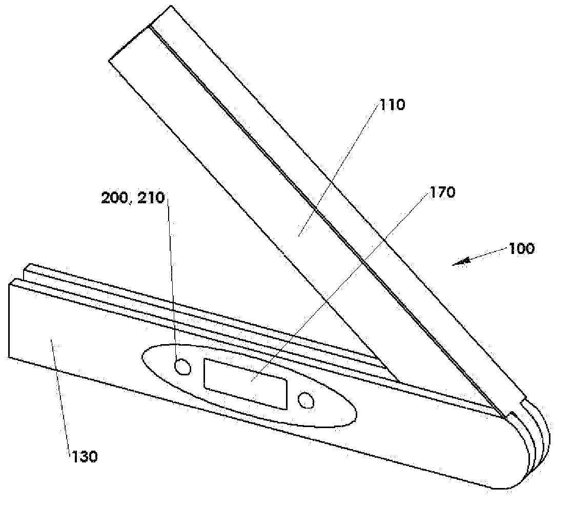
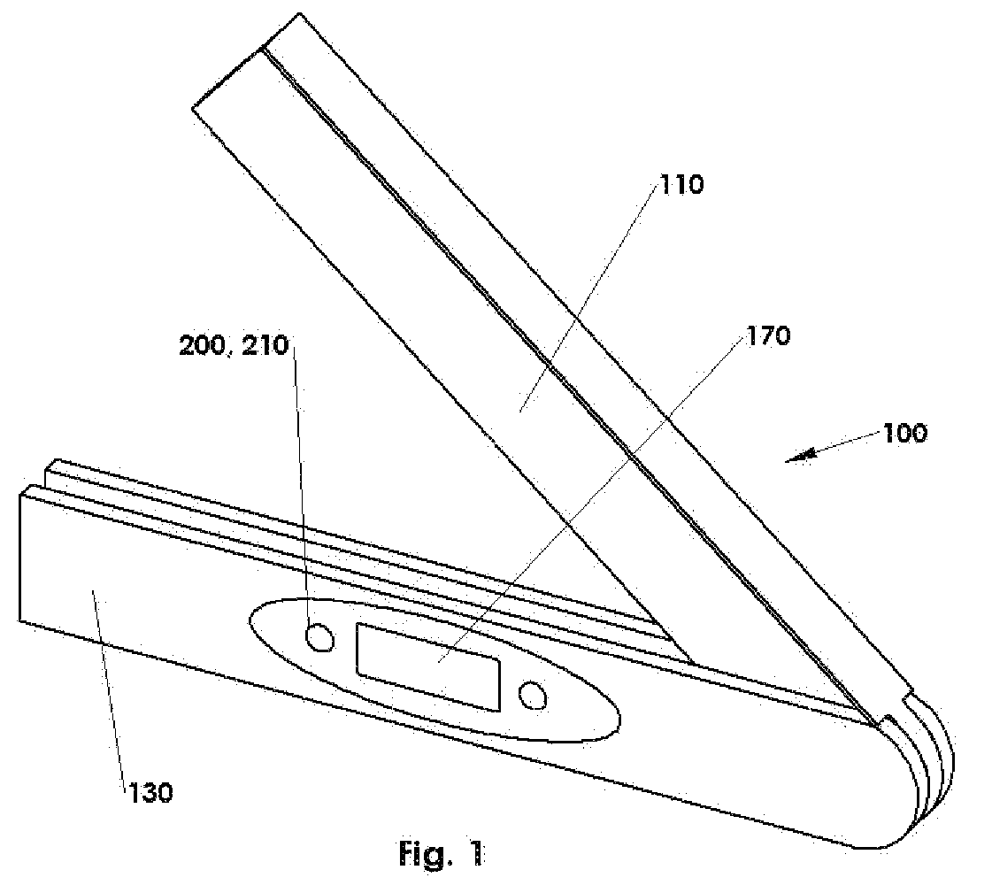
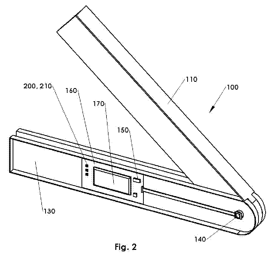
[0025]The present invention is an angle measuring device 100 with two pivotable arms that are connected at a common point. The first arm 110 contains a rigidly linked shaft 120 which connects the first arm 110 to a second arm 130 in such a way that the second arm 130 can rotate on the shaft 120 with reference to the first arm 110. A first electronic sensor 140 is used to determine the angle between the first arm 110 and the second arm 130. This first electronic sensor 140 can be, for example, but is not limited to, a magnetic rotary encoder 145 or an optical rotary encoder. I...


PUM


Abstract

An angle measuring device with two pivotable arms connected at a common point is disclosed. The first arm contains a rigidly linked shaft which connects the first arm to a second arm rotatable relative to the first arm. A first electronic sensor, such as a magnetic rotary encoder, determines the angle between the arms. Optionally, a second electronic sensor, such as an accelerometer, determines the angle of orientation of an arm with reference to the plane of the Earth. The microcontroller can be used to aggregate the output of the magnetic rotary encoder with the accelerometers, so as to calculate the angle from the plane of the Earth up to the first arm of the angle measuring device.

Description

CROSS-REFERENCE TO RELATED APPLICATION[0001]This application claims the benefit of the following U.S. Provisional Patent Application No. 60 / 767,541, filed Jun. 8, 2006, which is hereby incorporated by reference in its entirety.BACKGROUND OF THE INVENTION[0002]The present invention relates to angle measuring devices, and more specifically to an electronic angle measuring device.DESCRIPTION OF THE RELATED ART[0003]In the construction, surveying, engineering, medical, and manufacturing fields, it is common practice to use a measurement tool to capture or establish angular measurements.[0004]One such angle measuring device is disclosed in U.S. Pat. No. 4,513,512, issued to Fischer. Fischer describes an angle-measuring instrument which includes two arms, which are interconnected in such a way that they can be pivoted about a common shaft, and an indicator for the angle of spread of the two arms. The shaft is rigidly connected with one of the arms, and drives the drive gear of a transmiss...

Claims


Application Information

Patent Timeline
IPC IPC(8): B43L7/10
CPCG01B7/30
Inventor CERWIN, JOHN
Owner CERWIN JOHN
Why Eureka
Try Eureka