Non-rotating Pick with a Pressed in Carbide Segment

Active Publication Date: 2008-02-14
SCHLUMBERGER TECH CORP
View PDF98 Cites 70 Cited by
  • Summary
  • Abstract
  • Description
  • Claims
  • Application Information

AI Technical Summary

Benefits of technology

[0009] In another aspect of the present invention a high impact resistant tool has a superhard material bonded to a cemented metal carbide substrate at a non-planar interface. The cemented metal carbide substrate is bonded to a front end of a cemented

Problems solved by technology

Formation degradation, such as asphalt milling, minin

Method used


Image

  • Non-rotating Pick with a Pressed in Carbide Segment
  • Non-rotating Pick with a Pressed in Carbide Segment
  • Non-rotating Pick with a Pressed in Carbide Segment

Examples


Embodiment Construction

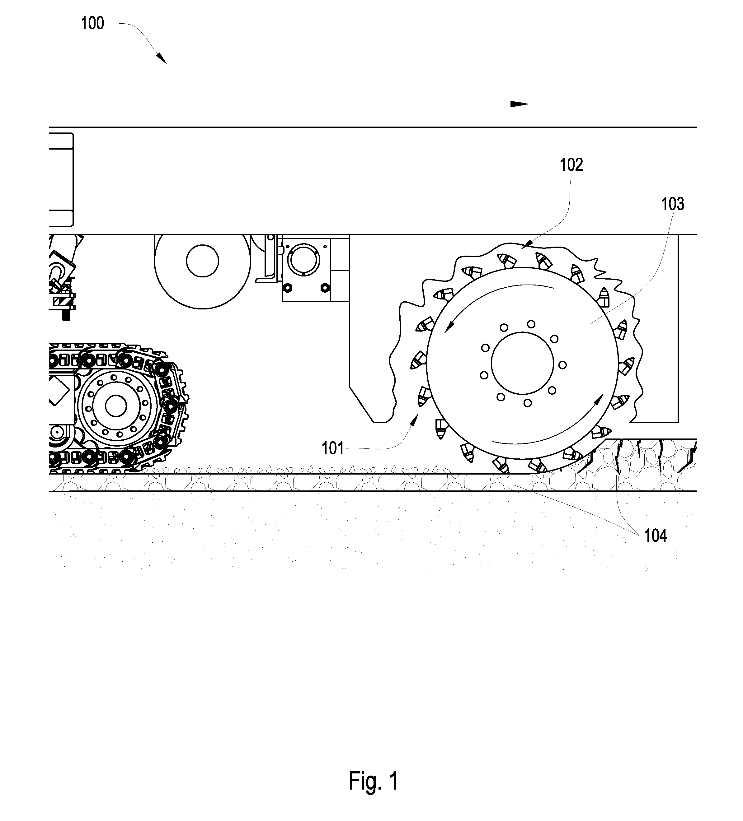
[0019]FIG. 1 is a cross-sectional diagram of an embodiment of a plurality of tools 101 attached to a rotating drum 103 connected to the underside of a pavement recycling machine 100. The recycling machine 100 may be a cold planer used to degrade man-made formations 104 such as pavement. Tools 101 may be rotationally fixed to the drum 103 bringing the tools 101 into contact with the formation 104. A holder 102 or block is attached to the rotating drum 103, and the tool 101 is inserted into the holder 102. The holder 102 or block may hold the tool 101 at an angel offset from the direction of rotation, such that the tool 101 engages the pavement at a preferential angle. The tool 101 may be rotationally fixed to the rotating drum 103.

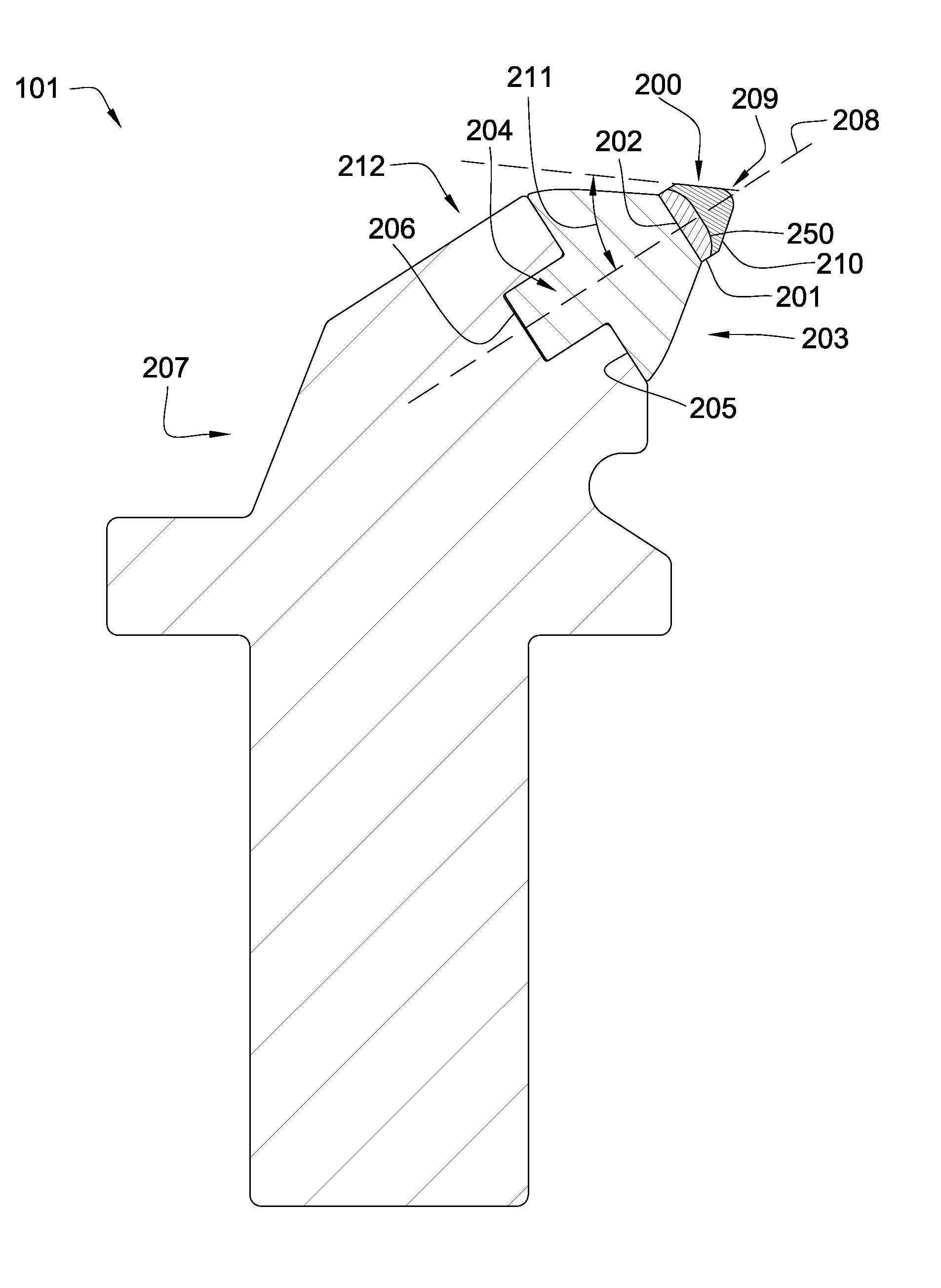
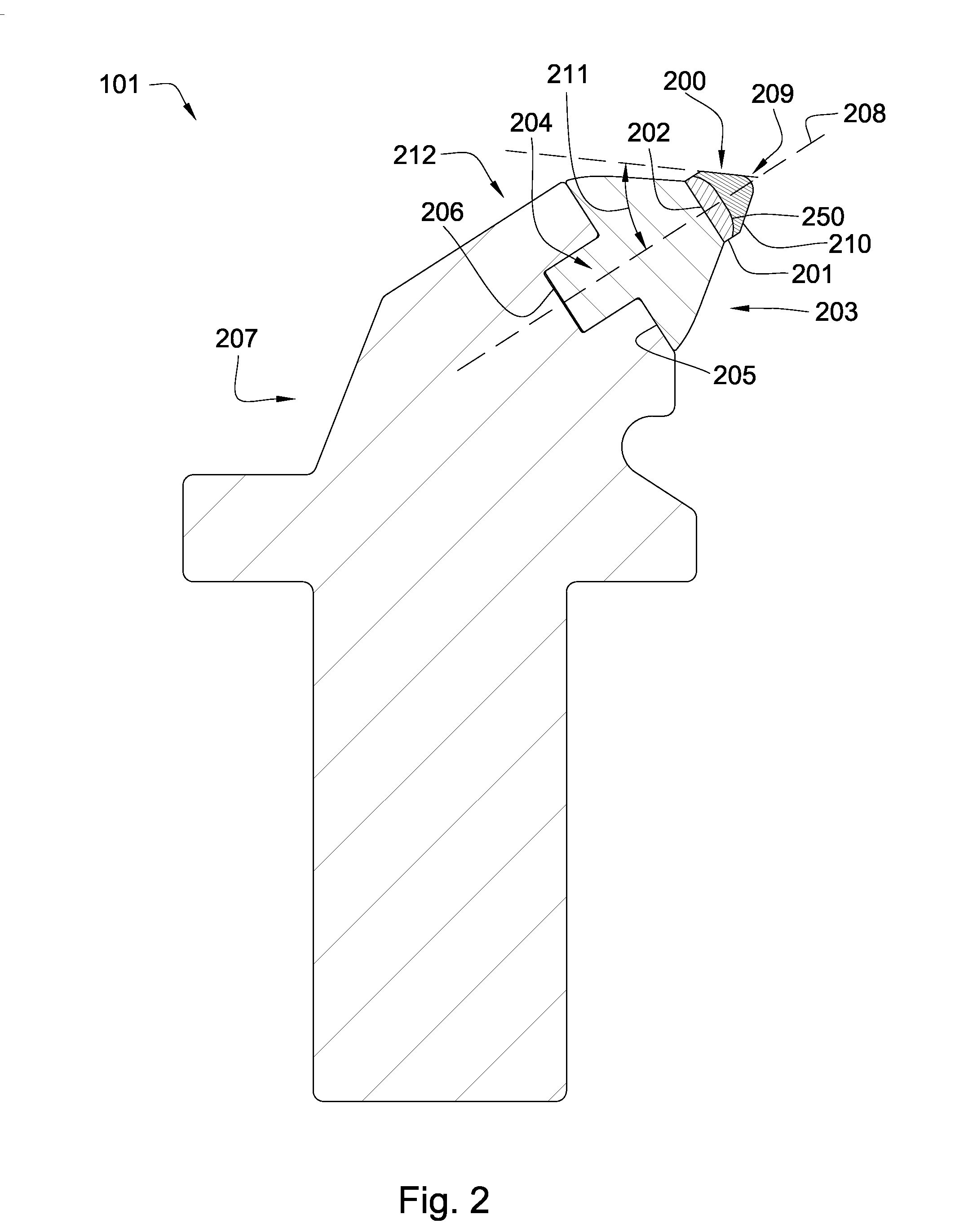
[0020]FIG. 2 illustrates a tool 101 having a superhard material 200 bonded to a cemented metal carbide substrate 201 at a non-planar interface 250. The cemented metal carbide substrate 201 is bonded to a front end 202 of a cemented metal carbide segment 20...


PUM


Abstract

In one aspect of the present invention, a high impact resistant tool has a superhard material bonded to a cemented metal carbide substrate at a non-planar interface. The cemented metal carbide substrate is bonded to a front end of a cemented metal carbide segment. A stem formed in the base end of the carbide segment opposite the front end is press fit into a bore of a steel body. The steel body is rotationally fixed to a drum adapted to rotate about its axis.

Description

CROSS REFERENCE TO RELATED APPLICATIONS [0001] This application is a continuation-in-part of U.S. patent application Ser. No. 11 / 871,722 which was filed on Oct. 12, 2007. U.S. patent application Ser. No. 11 / 871,722 is a continuation-in-part of U.S. patent application Ser. No. 11 / 844,586, which was filed on Aug. 24, 2007. U.S. patent application Ser. No. 11 / 844,586 is a continuation-in-part of U.S. patent application Ser. No. 11 / 829,761, which was filed on Jul. 27, 2007. U.S. patent application Ser. No. 11 / 829,761 is a continuation in-part of U.S. patent application Ser. No. 11 / 773,271 which was filed on Jul. 3, 2007. U.S. patent application Ser. No. 11 / 773,271 is a continuation-in-part of U.S. patent application Ser. No. 11 / 766,903 filed on Jun. 22, 2007. U.S. patent application Ser. No. 11 / 766,903 is a continuation of U.S. patent application Ser. No. 11 / 766,865 filed on Jun. 22, 2007. U.S. patent application Ser. No. 11 / 766,865 is a continuation-in-part of U.S. patent application S...

Claims


Application Information

Patent Timeline
IPC IPC(8): E21B10/36E21B10/46
CPCE21C35/183E21C35/19E21C2035/1809E21C2035/1806E21C35/1933E21C35/1833E21C35/1831
Inventor HALL, DAVID R.CROCKETT, RONALDBAILEY, JOHNJEPSON, JEFF
Owner SCHLUMBERGER TECH CORP
Why Eureka
Try Eureka