Spinal fusion implant

a technology of spinal fusion and implant, which is applied in the field of spinal implants, can solve the problems of difficult insertion and positioning of implants, complicated procedures, etc., and achieve the effect of greater ease and flexibility in inserting and positioning implants

Active Publication Date: 2008-03-06
DEPUY SYNTHES PROD INC
View PDF24 Cites 99 Cited by
  • Summary
  • Abstract
  • Description
  • Claims
  • Application Information

AI Technical Summary

Benefits of technology

[0006]The present invention provides a device and methodology for use in spinal fusion surgeries. An implant, instrumentation, and methodology are provided for forming a rigid structure between adjoining vertebrae in a patient. The implant is a cage defined by at least a first end, second end, first side, and second side surface. The cage incorporates one or more flexible joints that a...

Problems solved by technology

The T-PLIF technique avoids damage to the nerve structures such as the dura, cauda equine, and the nerve root, but the trans...

Method used


Image

  • Spinal fusion implant
  • Spinal fusion implant
  • Spinal fusion implant

Examples


Embodiment Construction

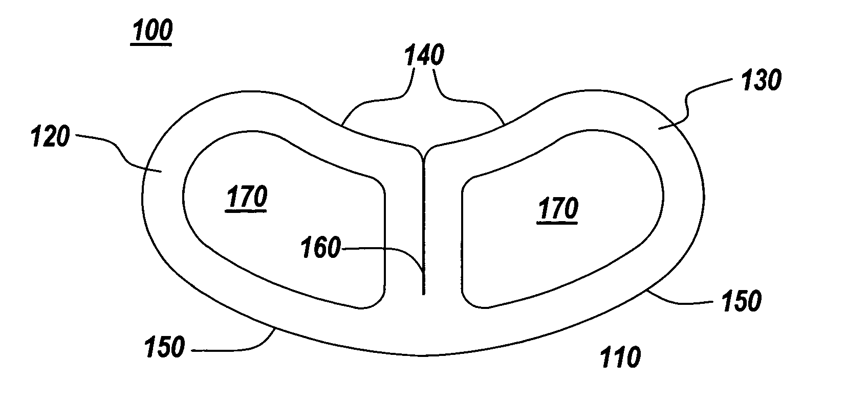
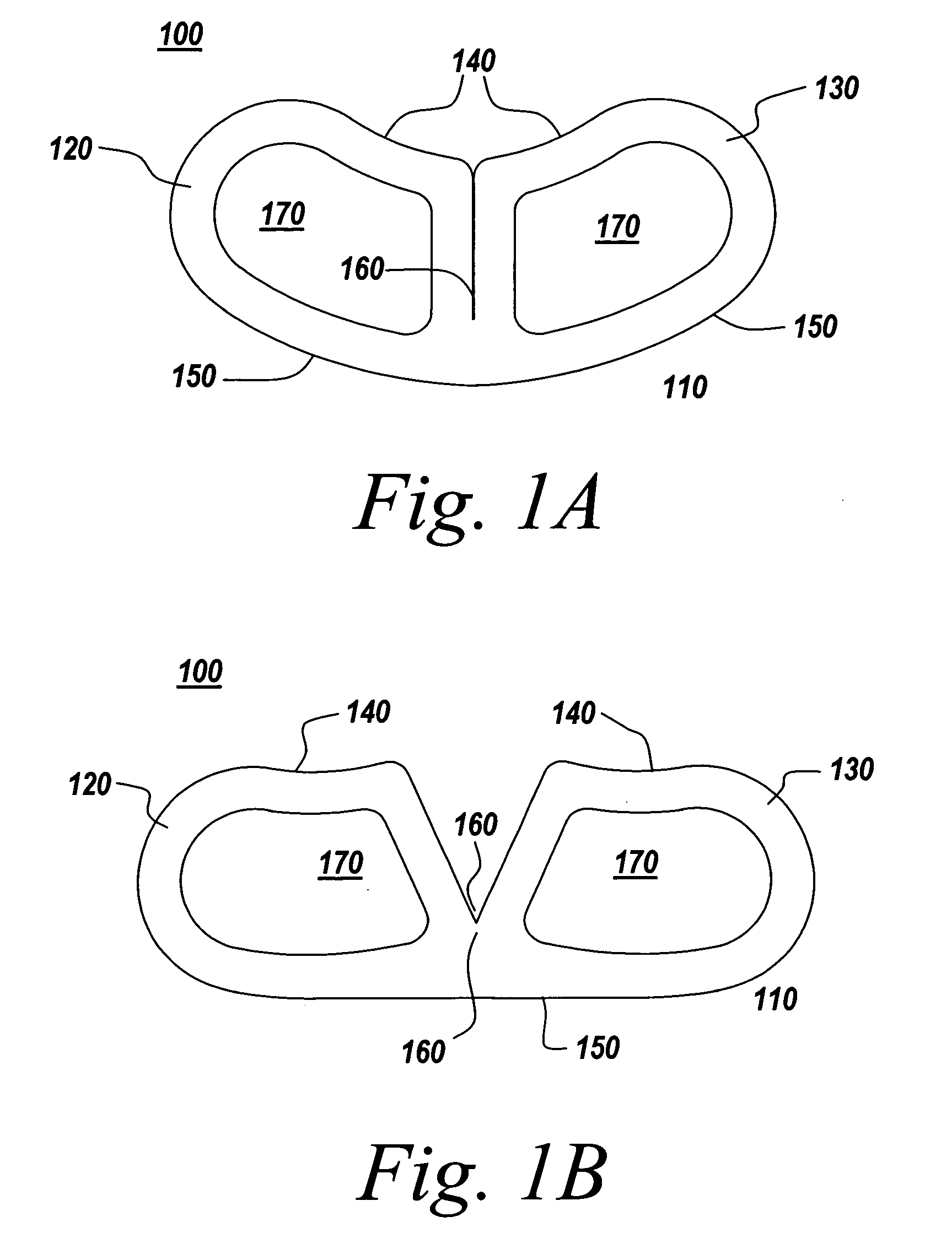
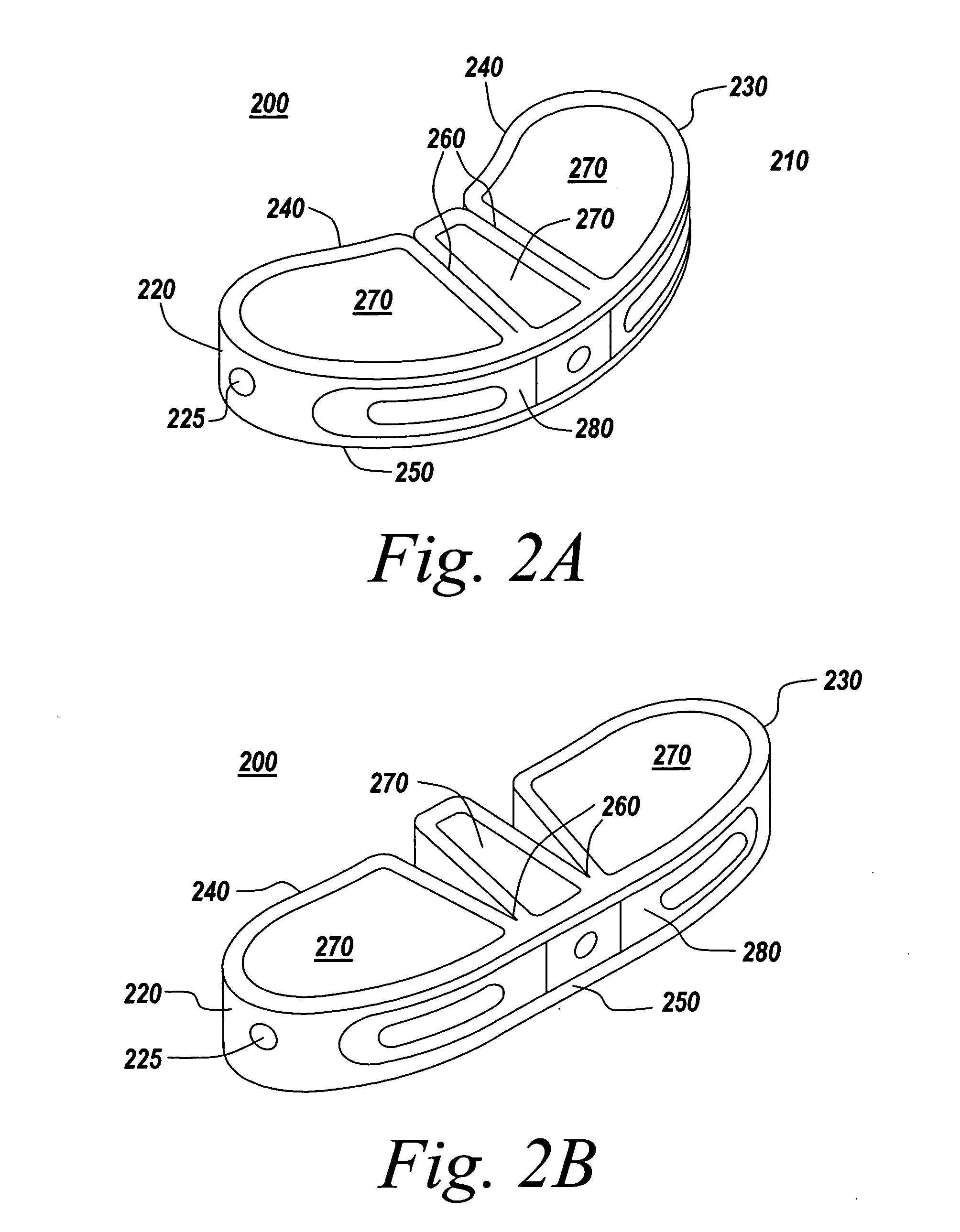
[0022]The present invention provides an improved surgical implant and method for performing spinal fusion surgery in a patient. The implant comprises a cage having one or more flexible joints. The cage is defined by at least a first end, second end, first side, and second side surface. The first and second side surfaces extend substantially parallel to each other to span a space between adjoining vertebrae and the first and second ends interconnect the first side surface and the second side surface. The one or more flexible joints allow the cage to be deformed for insertion into a patient. The ability to deform the cage allows a greater ease and flexibility in inserting and positioning the implant. For example, a larger implant can to be used in minimally invasive surgery (MIS) techniques because the cage can be transformed to a smaller profile to pass through the smaller access ports used in minimally invasive surgery. In certain embodiments the implant may further have surface con...


PUM


Abstract

The present invention provides a device and methodology for use in spinal fusion surgeries. An implant is proved for forming a rigid structure between adjoining vertebrae in a patient. The implant is a cage defined by at least a first end, second end, first side, and second side surface, wherein first and second side surfaces extend substantially parallel to each other to span a space between adjoining vertebrae and first and second ends interconnect said first side surface and second side surface. The cage incorporates one or more flexible joints that allow the cage to be deformed for insertion into a patient. The ability to deform the cage allows a greater ease and flexibility in inserting and positioning the implant.

Description

FIELD OF THE INVENTION[0001]The present invention relates to a spinal implant, the accompanying instrumentation and the method of use of both. More particularly, the present invention relates to a device and instrumentation for use in a minimally invasive vertebral fusion procedure.BACKGROUND OF THE INVENTION[0002]Spinal fusion surgeries that use bone graft material to promote specific vertebrae to grow together into a solid and stable construct are a common method of treating patients with severe back pain. In posterior lumbar interbody fusion (PLIF), damaged disk material is removed and one or more implants are inserted posteriorly to promote bone growth from vertebral body to vertebral body to bridge the gap left by the removed material.[0003]A larger implant better fills the intervertibral space and distributes compressive loads. A larger implant also reduces the need for multiple implants, which may require multiple approaches to insertion and placement. However, Minimally Inva...

Claims


Application Information

Patent Timeline
IPC IPC(8): A61F2/44
CPCA61F2/4465A61F2/4455A61F2/4611A61F2002/2835A61F2002/30133A61F2002/30383A61F2002/30471A61F2002/30538A61F2002/30571A61F2002/30579A61F2002/30784A61F2002/4415A61F2002/4635A61F2220/0025A61F2220/0091A61F2230/0015A61F2250/0006A61F2/447A61F2230/0095A61F2250/0004A61F2/442A61F2/4425A61F2002/30565
Inventor GARNER, RONALDDZIEDZIC, SARAMAHONEY, MICHAELRUBERTE, RAMON
Owner DEPUY SYNTHES PROD INC
Why Eureka
Try Eureka