Shipping container for flowable material and flexible tank therefor

a technology of flexible tanks and flowable materials, applied in the field of shipping containers, can solve the problems of adversely affecting the quality of oxygen sensitive materials, and otherwise desirable transportation systems less suitable for wine shipment, so as to minimize oxygen transmission and minimize oxygen transmission

Inactive Publication Date: 2008-08-14
SCHOLLE CORP
View PDF44 Cites 10 Cited by
  • Summary
  • Abstract
  • Description
  • Claims
  • Application Information

AI Technical Summary

Benefits of technology

[0024]In another aspect of the invention, the invention comprises a flexible tank for use in association with a rigid shipping container for the transport of flowable material. The flexible tank comprises an oxygen sensitive flowable material. The flexible tank is positionable within the rigid shipping container. The flexible tank includes a film having a plurality of seals to define a cavity, and a dispensing means for dispensing a flowable material positioned within the cavity. The film comprises a layer having a co-extruded blend of HDPE and TPE, to, in turn minimize oxygen transmission within the film.
[0025]In another aspect of the invention, the invention comprises a shipping container for flowable material which includes a large rigid shipping container and a flexible tank positioned within the rigid shipping container. The shipping conta...

Problems solved by technology

Furthermore, a great cost savings is realized inasmuch as the construction costs of ISO tanks are typically quite expensive when compared to a standard shipping container and a flexible tank.
While such advantages are leading a revolution in the shipment of flowable materials, there have been drawbacks.
Such an OTR is quite high and can adversely affect the quality of oxygen sensitive materials when shipped any appreciable distances.
For example, such an OTR makes the otherwise desirable transport system less suitable for the satisfactory shipment...

Method used


Image

  • Shipping container for flowable material and flexible tank therefor
  • Shipping container for flowable material and flexible tank therefor
  • Shipping container for flowable material and flexible tank therefor

Examples


Embodiment Construction

[0033]While this invention is susceptible of embodiment in many different forms, there is shown in the drawings and described herein in detail a specific embodiment with the understanding that the present disclosure is to be considered as an exemplification of the principles of the invention and is not intended to limit the invention to the embodiment illustrated.

[0034]It will be understood that like or analogous elements and / or components, referred to herein, may be identified throughout the drawings by like reference characters. In addition, it will be understood that the drawings are merely schematic representations of the invention, and some of the components may have been distorted from actual scale for purposes of pictorial clarity.

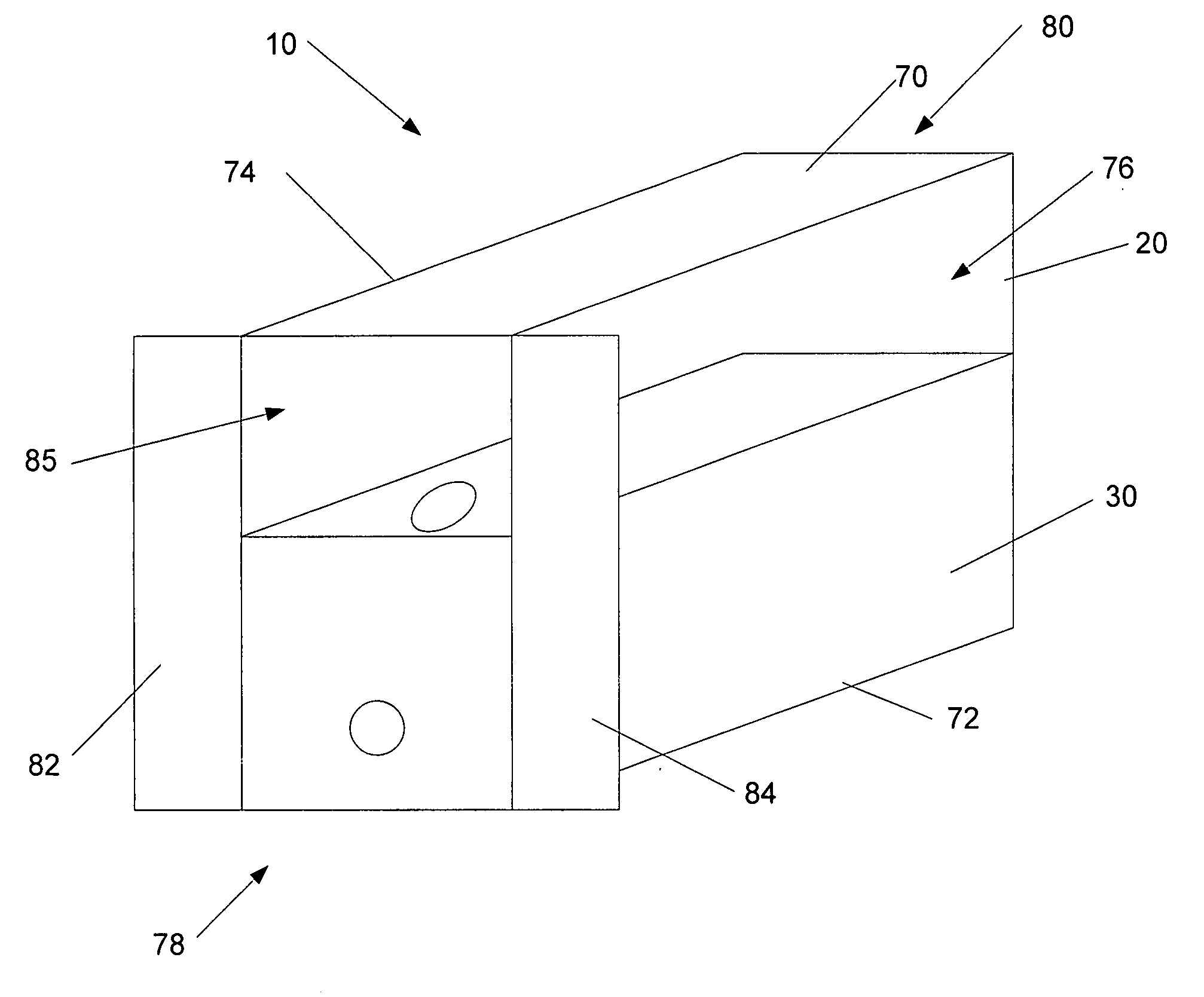
[0035]Referring now to the drawings and in particular to FIG. 1, a shipping container for flowable material is shown generally at 10. The shipping container includes a large rigid outer container 20 and inner flexible tank 30. The large rigid outer ...


PUM

PropertyMeasurementUnit
Thicknessaaaaaaaaaa
Thicknessaaaaaaaaaa
Thicknessaaaaaaaaaa

Abstract

A shipping container for flowable material including a large rigid shipping container and a flexible tank. The shipping container has a substantially rectangular cubic configuration with common attachment regions. The flexible tank is positionable within the rigid shipping container. The flexible tank includes a generally rectangular cubic configuration. At least certain dimensions of the flexible tank corresponding to dimensions of the large rigid shipping container so that the flexible tank has a generally form fit retention within the large rigid shipping container. The flexible tank further comprises a film which together with a plurality of seals defines a substantially rectangular cubic cavity. A dispensing means is provided which extends through the film for selectively placing the cavity in fluid communication with an outside dispenser. The film comprises a layer comprising a co-extruded blend of HDPE and TPE, to, in turn minimize oxygen transmission within the film.

Description

BACKGROUND OF THE INVENTION[0001]1. Field of the Invention[0002]The invention relates in general to shipping containers, and more particularly, to a shipping container for flowable material which comprises a large outer container (i.e., a common twenty foot shipping container, or the like) and an inner flexible tank. Furthermore, the invention is directed to a flexible tank used within the shipping container.[0003]2. Background Art[0004]Shipment of flowable material in large quantity over relatively long distances has increased over the last few decades. Whereas dry cargo has been essentially revolutionized in the last 40 years, with the introduction of the standard shipping container, the ISO tank has remained the common mode of transporting flowable materials.[0005]In the past several years, however, there has been a move toward the use of flexible tanks positioned and retained within standard shipping containers for transporting relatively large shipments of flowable materials. A...

Claims


Application Information

Patent Timeline
IPC IPC(8): B65D88/22
CPCB65D2590/046B65D90/046
Inventor BELLMORE, DAVID J.
Owner SCHOLLE CORP
Why Eureka
Try Eureka