

Attachment for a power tool guide rail
- Summary
- Abstract
- Description
- Claims
- Application Information
AI Technical Summary
Benefits of technology
Problems solved by technology
Method used
Image

Examples
Embodiment Construction
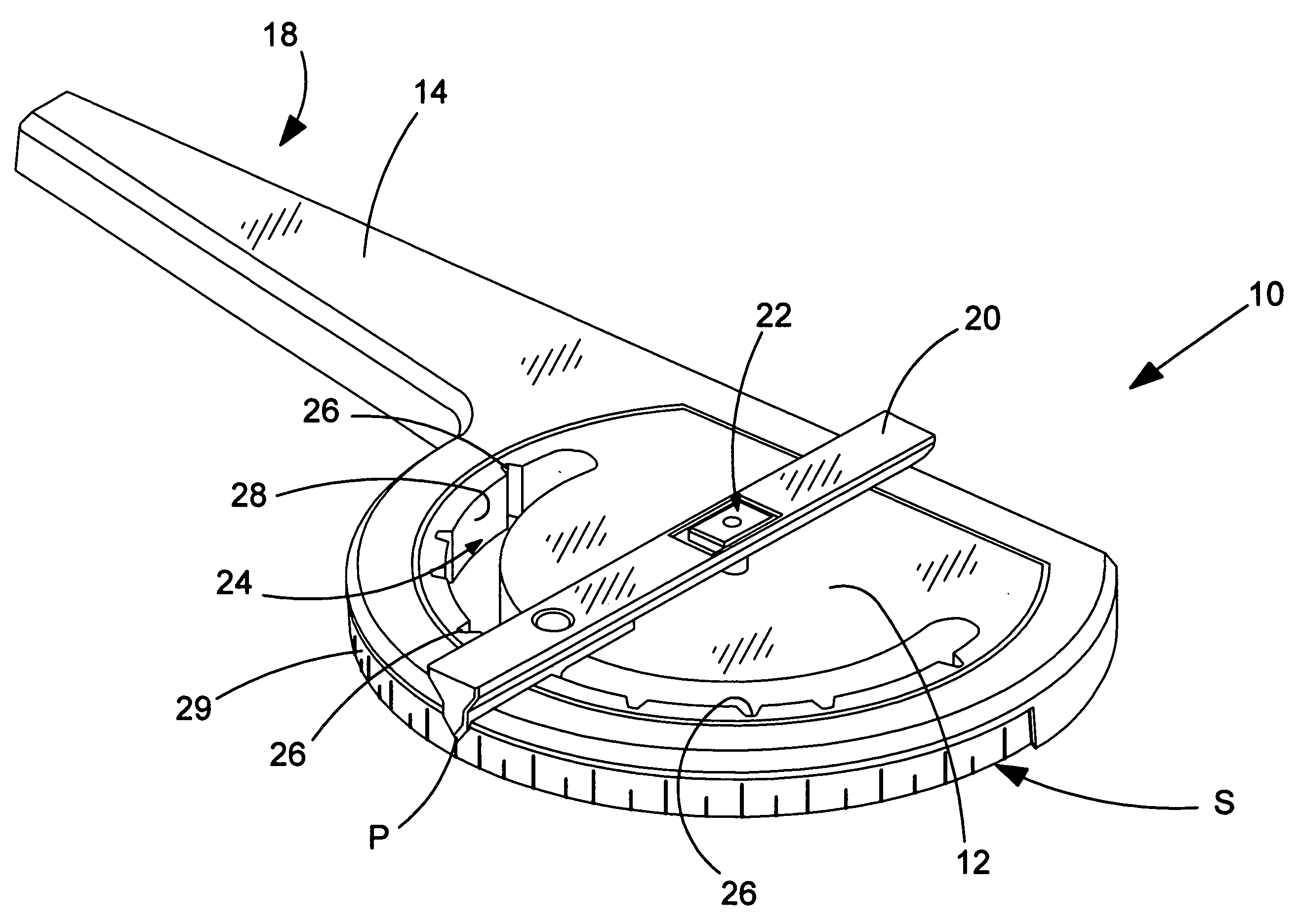
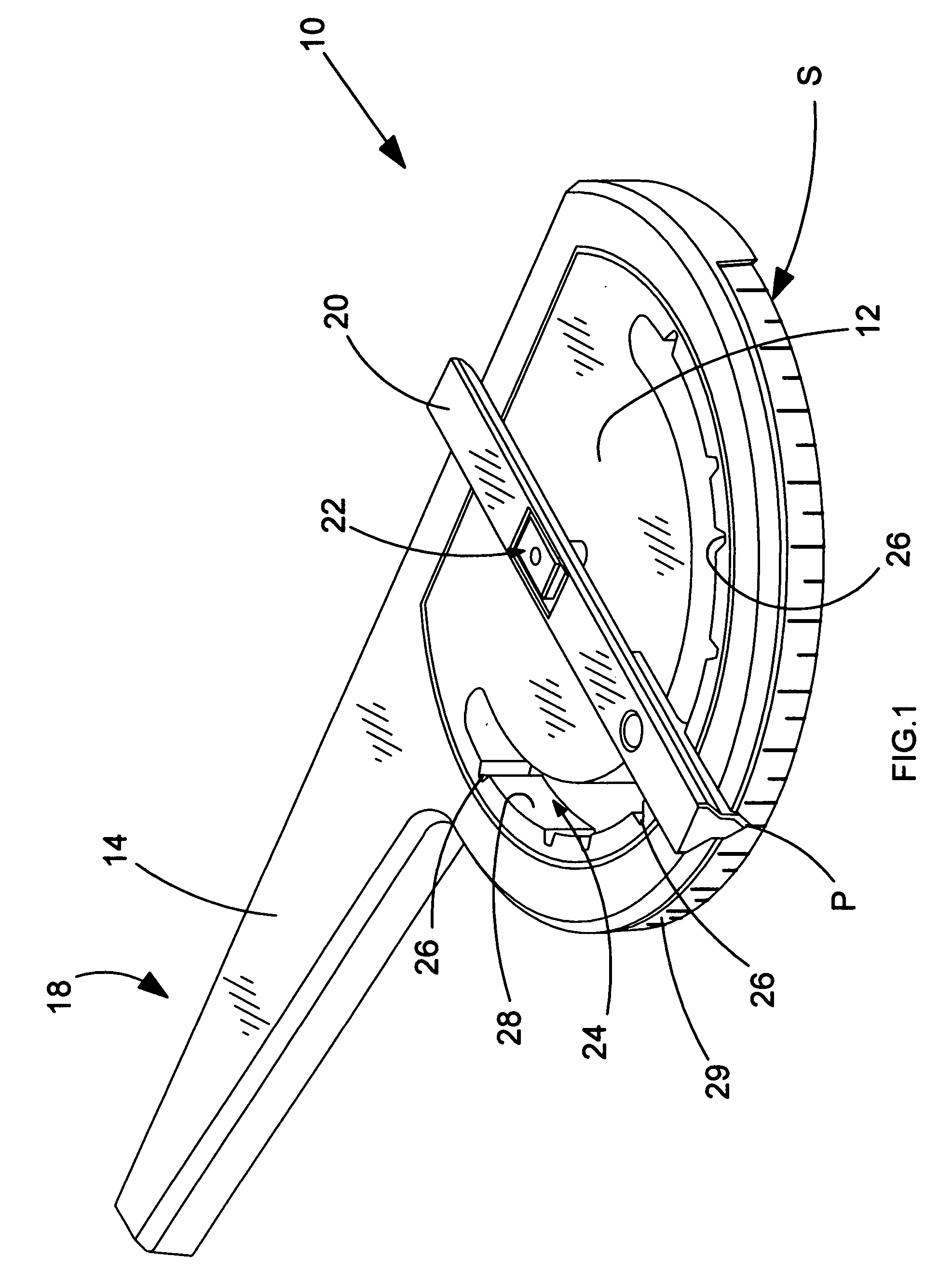
[0030]Prior art devices which are arranged to be detachable from guide rails suffer from the problem of the end-user being unable to ensure that the setsquare can be replaced on a guide rail such that the angle between an edge of the rail and a reference surface on the attachment is replicated accurately and repeatable. Being able to achieve accurate replication of angles set by the setsquare is a major requirement for the end-user, particularly for a professional workman. Furthermore, the professional end-user often requires their guide rail to have a degree of versatility whereby the guide rail can be used without the setsquare being attached, for instance. Thus, being able to remove a setsquare from the guide rail is required by the end-user.
[0031]With this in mind, and with reference to FIG. 1, a detachable setsquare 10 embodying the present invention is now described. The setsquare 10 preferably comprises a body portion 12 having an arm 14 extending therefrom. The arm comprises...
PUM
| Property | Measurement | Unit |
|---|---|---|
| Shape | aaaaa | aaaaa |
| Displacement | aaaaa | aaaaa |
Abstract
Description
Claims
Application Information