Breast pump

a breast pump and pump body technology, applied in the field of breast pumps, can solve the problems of deterioration of suction efficiency, difficult to clean the breast pump thoroughly, complicated and difficult disassembly, etc., and achieve the effects of improving milking effect, superior suction efficiency, and easy cleaning

Active Publication Date: 2008-10-02
PIGEON CORP
View PDF8 Cites 34 Cited by
  • Summary
  • Abstract
  • Description
  • Claims
  • Application Information

AI Technical Summary

Benefits of technology

[0012]According to an aspect of the disclosed subject matter, a breast pump can be provided that exhibits superior suction efficiency for forming negative pressure, and in addition to negative pressure functions effectively to achieve a further increase in the milking effect, and is also easy to clean and has a comparative simple constitution.

Problems solved by technology

Hence, the space for forming the negative pressure used for milking is large, and therefore a large volume must be suctioned, leading to deterioration of the suction efficiency.
Further, since the space is formed in a location outside of the horn-shaped milking portion and the diaphragm is attached thereto, a diaphragm attachment structure is used which is complicated and difficult to dismantle.
Therefore, it is difficult to clean the breast pump thoroughly, which is inconvenient in terms of hygienic use.

Method used


Image

  • Breast pump
  • Breast pump
  • Breast pump

Examples


first embodiment

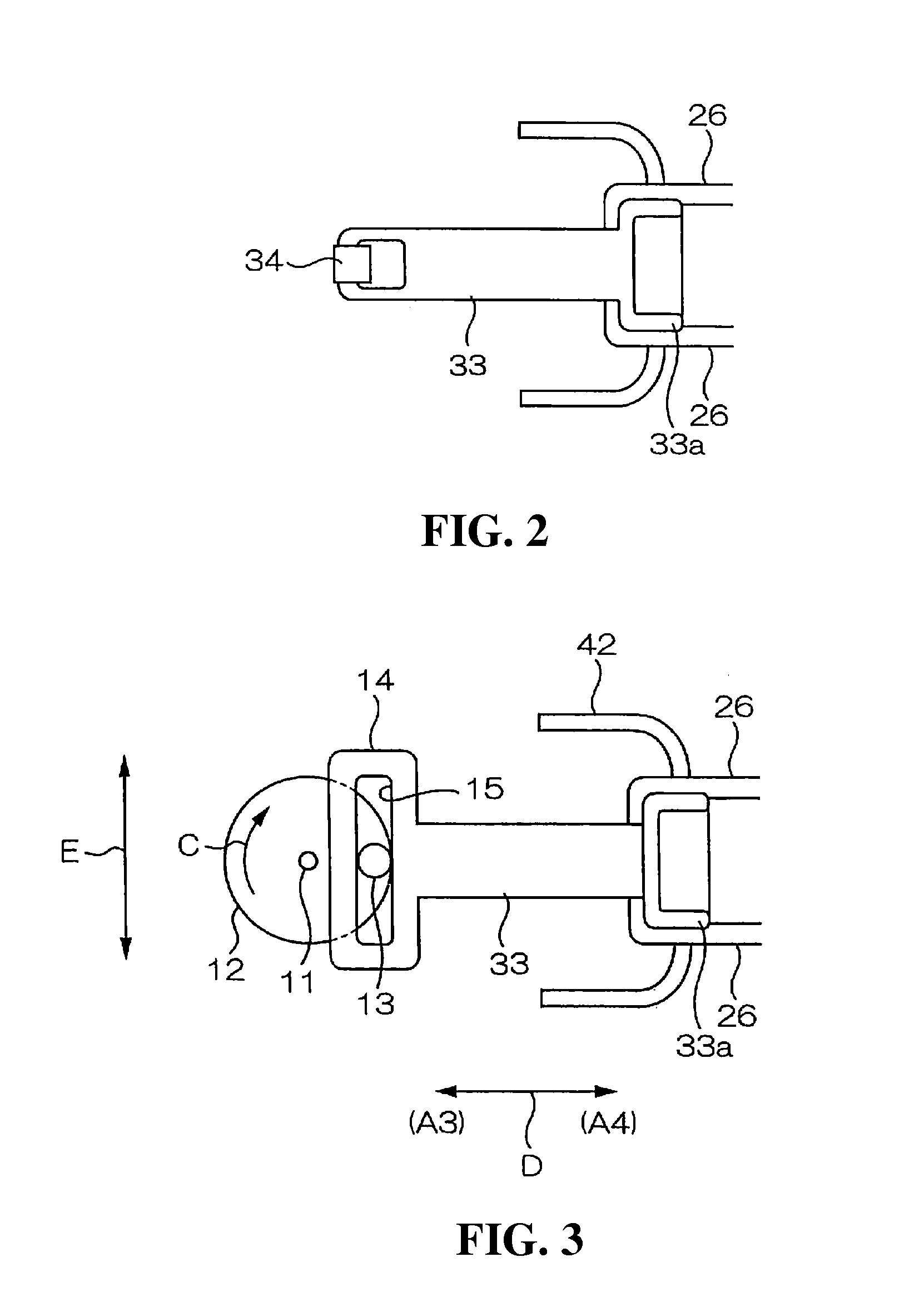
[0070]FIG. 3 is a schematic plan view of a modified example of the first embodiment, and shows a simplification of certain parts of a constitutional example in which the diaphragm portion 28 serving as the negative pressure generating portion is driven via the arm portion 33.

[0071]An attachment portion 14 is provided on the tip end of the arm portion 33, and an elongated hole 15 extending in an orthogonal direction to the extension direction of the arm portion 33 is formed in the attachment portion 14. A pin 13 provided near the outer periphery and forms an eccentric cam 12, the pin 13 is inserted into the elongated hole 15.

[0072]A rotary shaft of an electric motor or the like, for example, can be fixed to a drive shaft 11 in the center of the eccentric cam 12.

[0073]This modified example is constituted as described above such that when the drive shaft 11 rotates, causing the eccentric cam 12 to rotate in the direction of arrow C, the pin 13 of the eccentric cam 12 reciprocates withi...

second embodiment

[0075]Next, a second embodiment will be described.

[0076]FIGS. 4 to 6 are schematic sectional views showing parts of a breast pump according to the second embodiment.

[0077]In FIGS. 4 to 6, locations or structures having identical reference symbols as compared to those used in FIGS. 1 and 2 illustrating the first embodiment can share similar or identical constitutions, and therefore duplicate description thereof has been omitted.

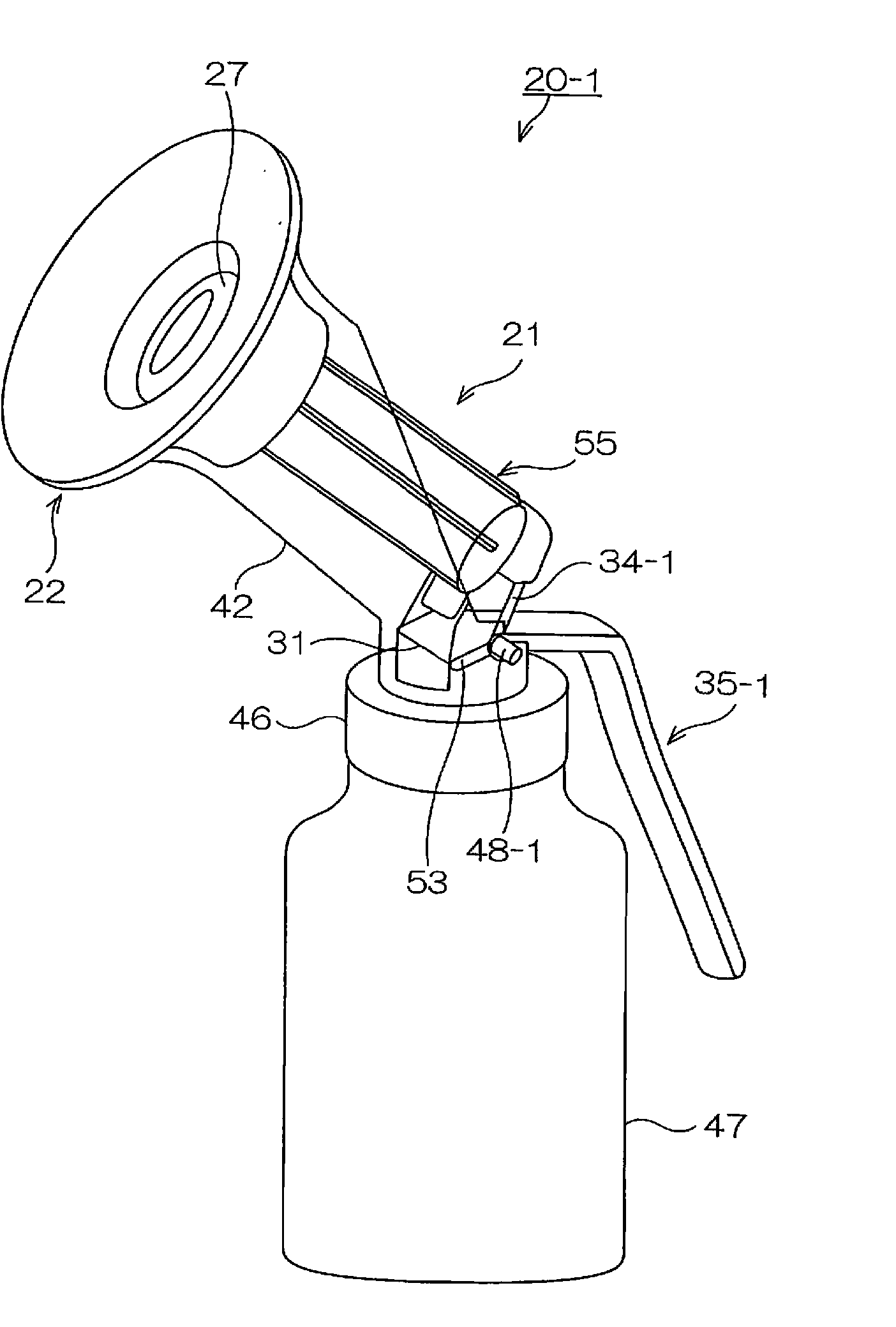
[0078]Negative pressure generating means 25-1 of the milking portion 22 of a breast pump 20-1 differ slightly from the first embodiment in the constitution of a support portion 26-1, which is formed as a continuation of the diaphragm portion 28 serving as the negative pressure generating means. More specifically, as shown in the drawings, the support portion 26-1 is slightly longer, and the arm portion 33 and shape maintaining portion 33a are therefore not formed. Further, a pocket-shaped or slit-shaped housing portion 51 is formed in a terminal end portion of...


PUM


Abstract

A breast pump can include a breast pump main body having a milking portion and negative pressure generating structure for generating negative pressure. A storing structure can be provided for storing expressed milk, and an opening/closing structure can be disposed between the breast pump main body and the storing structure for temporarily halting or permitting passage of the expressed milk into the storing structure. The milking portion can include a shape maintaining portion and a negative pressure generating portion that serves as a part of the negative pressure generating structure and can be attached to and detached from an inner side of the shape maintaining portion. At least one end of the negative pressure generating portion on an enlarged diameter side can include a flexible diaphragm portion and a pressing portion formed when a folded-back portion of the diaphragm portion passes an imaginary line of extension of a contact portion contacting the breast to press the breast, while the other end of the negative pressure generating portion is connected to the opening/closing structure.

Description

[0001]This application claims the priority benefit under 35 U.S.C. § 119 of Japanese Patent Application No. JP2007-81842 filed on Mar. 27, 2007, which is hereby incorporated in its entirety by reference.BACKGROUND[0002]1. Field[0003]The presently disclosed subject matter relates to a breast pump for expressing milk.[0004]2. Description of the Related Art[0005]Breast pumps having a horn-shaped milking portion with an enlarged diameter that is brought into contact with the breast of a mother, or in other words an enlarged-diameter milking portion, are widely used.[0006]In a well-known constitution for ensuring that the milk, which is formed into a mist by negative pressure generated during milking, does not leak out, a recess is provided in an upper end of a breast pump main body or the like and a deformable member such as a diaphragm is housed in the recess.[0007]More specifically, in a well-known manual breast pump disclosed in U.S. Pat. No. 5,749,850, a handle is connected to the d...

Claims


Application Information

Patent Timeline
Patent Type & Authority Applications(United States)
IPC IPC(8): A61M1/06
CPCA61M1/06A61M1/066A61M1/064A61M1/0697
Inventor YAMASHITA, DAISUKEOUSHI, YOSHIYUKI
Owner PIGEON CORP
Why Eureka
Try Eureka