Fixing device and image forming apparatus having the same

Active Publication Date: 2008-10-09
HEWLETT PACKARD DEV CO LP
View PDF3 Cites 37 Cited by
  • Summary
  • Abstract
  • Description
  • Claims
  • Application Information

AI Technical Summary

Benefits of technology

[0012]The present general inventive concept provides a fixing device in which a nip zone and a heating unit are separat

Problems solved by technology

However, since the heating roller 20 has a large thermal capacity and applies heat not only to the nip zone N but also to the entire surface of the heating roller 20, a long period of time is required to raise the temperature.
Additionally, a width of the heating unit 60 is increased, and thus it is possible to increase the width of the nip zone N. How

Method used


Image

  • Fixing device and image forming apparatus having the same
  • Fixing device and image forming apparatus having the same
  • Fixing device and image forming apparatus having the same

Examples


Embodiment Construction

[0052]Reference will now be made in detail to the exemplary embodiments of the present general inventive concept, examples of which are illustrated in the accompanying drawings, wherein like reference numerals refer to the like elements throughout. The exemplary embodiments are described below in order to explain the present general inventive concept by referring to the figures.

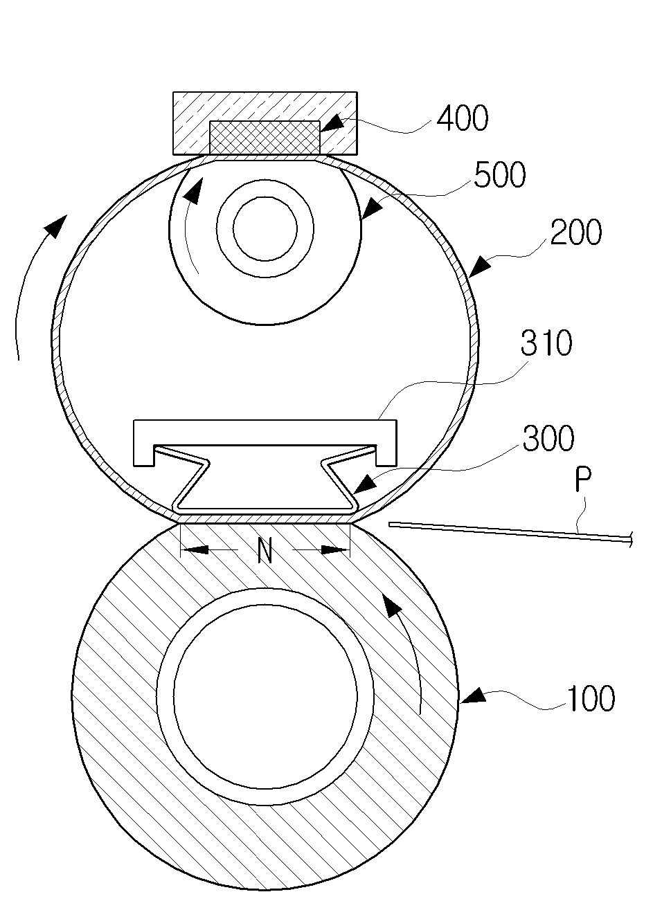
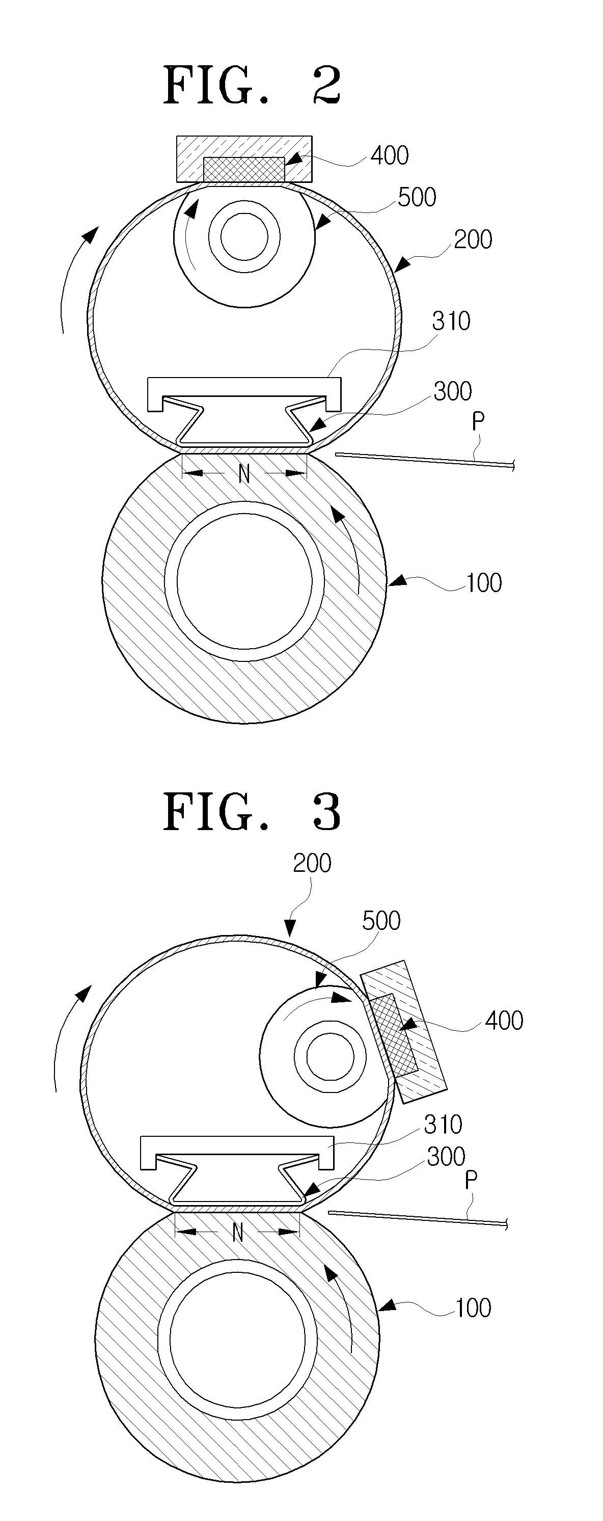
[0053]FIG. 2 is a sectional view schematically illustrating a fixing device usable with an image forming apparatus according to an exemplary embodiment of the present general inventive concept, FIG. 3 is a sectional view illustrating a position of a heating unit illustrated in FIG. 2, FIG. 4 is a sectional view illustrating positions of a heating unit and a supporting roller illustrated in FIG. 3, andFIG. 5 is a sectional view illustrating a guide member mounted in a fixing belt in the fixing device of FIG. 2.

[0054]As illustrated in FIGS. 2 through 5, the fixing device according to the exemplary embodiment of...


PUM


Abstract

A fixing device includes a fixing roller, a fixing belt which is made to rotate by a rotation force received from the fixing roller, a nip forming unit to form a nip zone at a contact area between the fixing roller and the fixing belt, and a first heating unit, which is separated from the nip zone, to apply heat to the fixing belt. The nip zone and the heating unit are separated, so that the heating unit can be prevented from being broken as a result of the pressurization and thermal deformation.

Description

CROSS-REFERENCE TO RELATED APPLICATIONS[0001]This application claims priority under 35 U.S.C. § 119 (a) of Korean Patent Application No. 10-2007-0033292, filed on Apr. 4, 2007, in the Korean Intellectual Property Office, the disclosure of which is incorporated herein by reference in its entirety.BACKGROUND OF THE INVENTION[0002]1. Field of the Invention[0003]The present general inventive concept relates to an image forming apparatus. More particularly, the present general inventive concept relates to a fixing device that fixes a toner image onto a printing medium, and an image forming apparatus having the fixing device.[0004]2. Description of the Related Art[0005]Image forming apparatuses, such as printers, copiers, scanners, multi-function machines, and the like, include fixing devices which fix developer images, such as toner images, which are transferred onto sheets of paper by transferring devices, which are widely known to those skilled in the art.[0006]In order to meet the rec...

Claims


Application Information

Patent Timeline
IPC IPC(8): G03G15/20
CPCG03G15/2064G03G2215/2035G03G15/2053
Inventor SHIN, SU-HOKIM, HWAN-GUEMSEOL, DONG-JINLEE, DONG-WOOKIM, TAE-GYUJUNG, CHANG-HOON
Owner HEWLETT PACKARD DEV CO LP
Why Eureka
Try Eureka