
Four pinion differential with cross pin retention unit and related method
a cross-pin retention unit and differential technology, applied in the direction of differential gearings, belts/chains/gearrings, gearings, etc., can solve the problems of complex and/or costly coupling of the first and second pinion shafts to the differential housing
- Summary
- Abstract
- Description
- Claims
- Application Information
AI Technical Summary
Benefits of technology
Problems solved by technology
Method used
Image

Examples
Embodiment Construction
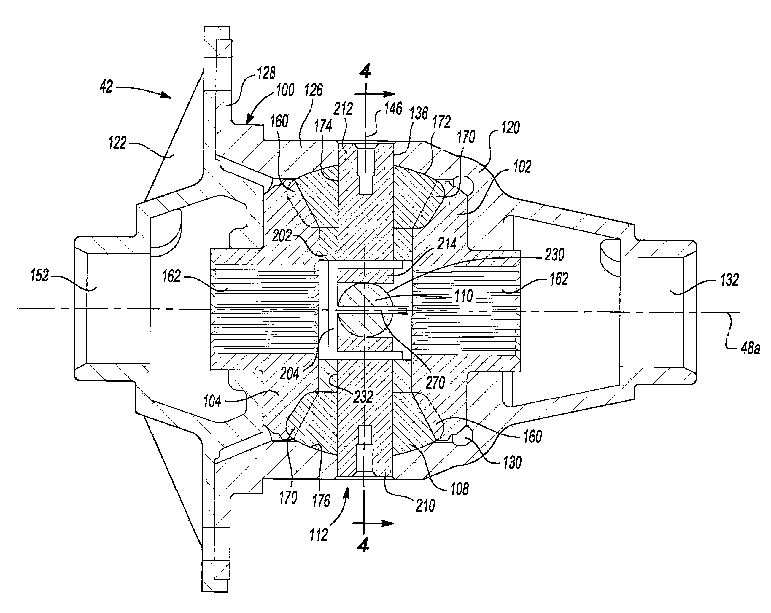
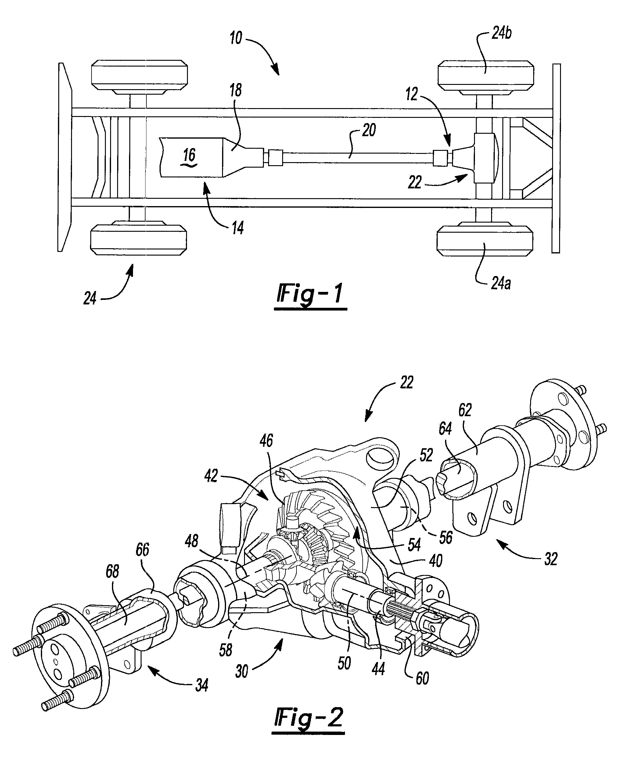
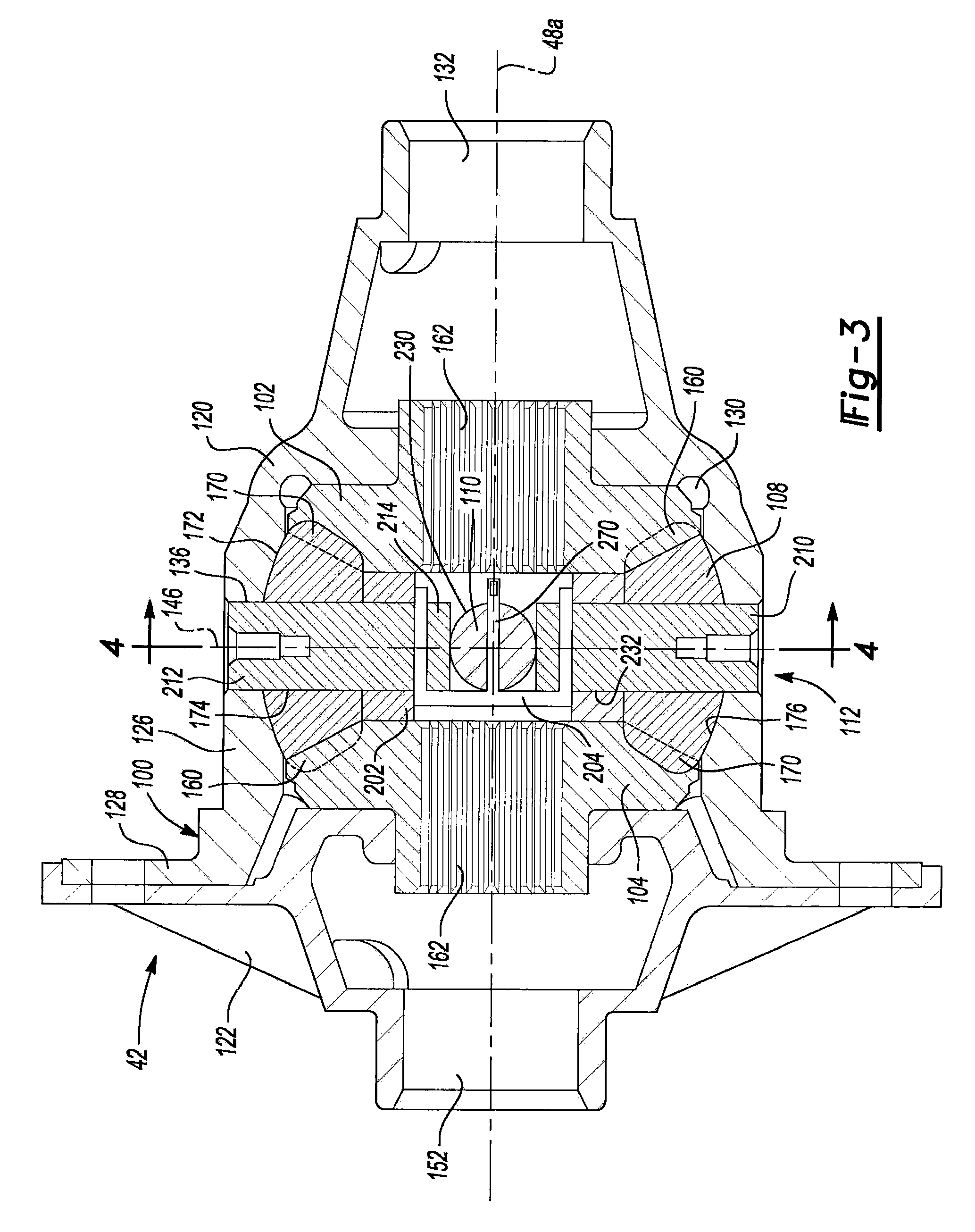
[0022]With reference to FIG. 1 of the drawings, a vehicle having a differential assembly that is constructed in accordance with the teachings of the present disclosure is generally indicated by reference numeral 10. The vehicle 10 can include a driveline 12 that is drivable via a connection to a power train 14. The power train 14 can include an engine 16 and a transmission 18. The driveline 12 can include a drive shaft 20, a rear axle 22 and a plurality of wheels 24. The engine 16 can be mounted in an in-line or longitudinal orientation along the axis of the vehicle 10 and its output can be selectively coupled via a conventional clutch to the input of the transmission 18 to transmit rotary power (i.e., drive torque) therebetween. The input of the transmission 18 can be commonly aligned with the output of the engine 16 for rotation about a rotary axis. The transmission 18 can also include an output and a gear reduction unit. The gear reduction unit can be operable for coupling the tr...
PUM
 Abstract
Description
Claims
Application Information