
Spacer pin arrangement for helical gear differential

a technology of spacer pins and differential gears, applied in the field of spacer pins, can solve problems such as incompatibility

Active Publication Date: 2009-11-03
AMERICAN AXLE & MFG
View PDF30 Cites 10 Cited by
  • Summary
  • Abstract
  • Description
  • Claims
  • Application Information

AI Technical Summary

Benefits of technology

"The present invention provides an axle assembly for a vehicle that includes a pair of axleshafts and a differential assembly having a differential case, a pair of side gears, and a spacer pin assembly. The spacer pin assembly includes a spacer ring and a cross pin that is fixedly but removably coupled to the differential case. The cross pin is inserted through the spacer ring and is retained within the spacer pin apertures. The technical effect of this invention is to provide a more stable and secure axle assembly that reduces movement of the axles in one direction and allows for independent movement of the side gears."

Problems solved by technology

However, because the access window is provided in the differential case, there tends to be incompatibility issues with placement of the pinion pairs.

Method used


Image

  • Spacer pin arrangement for helical gear differential
  • Spacer pin arrangement for helical gear differential
  • Spacer pin arrangement for helical gear differential

Examples


Embodiment Construction

[0025]The following description of the preferred embodiments is merely exemplary in nature and is in no way intended to limit the disclosure, its application, or uses. The differential assembly according to the present teachings may be utilized with a wide variety of applications and is not intended to be specifically limited to the particular application recited herein.

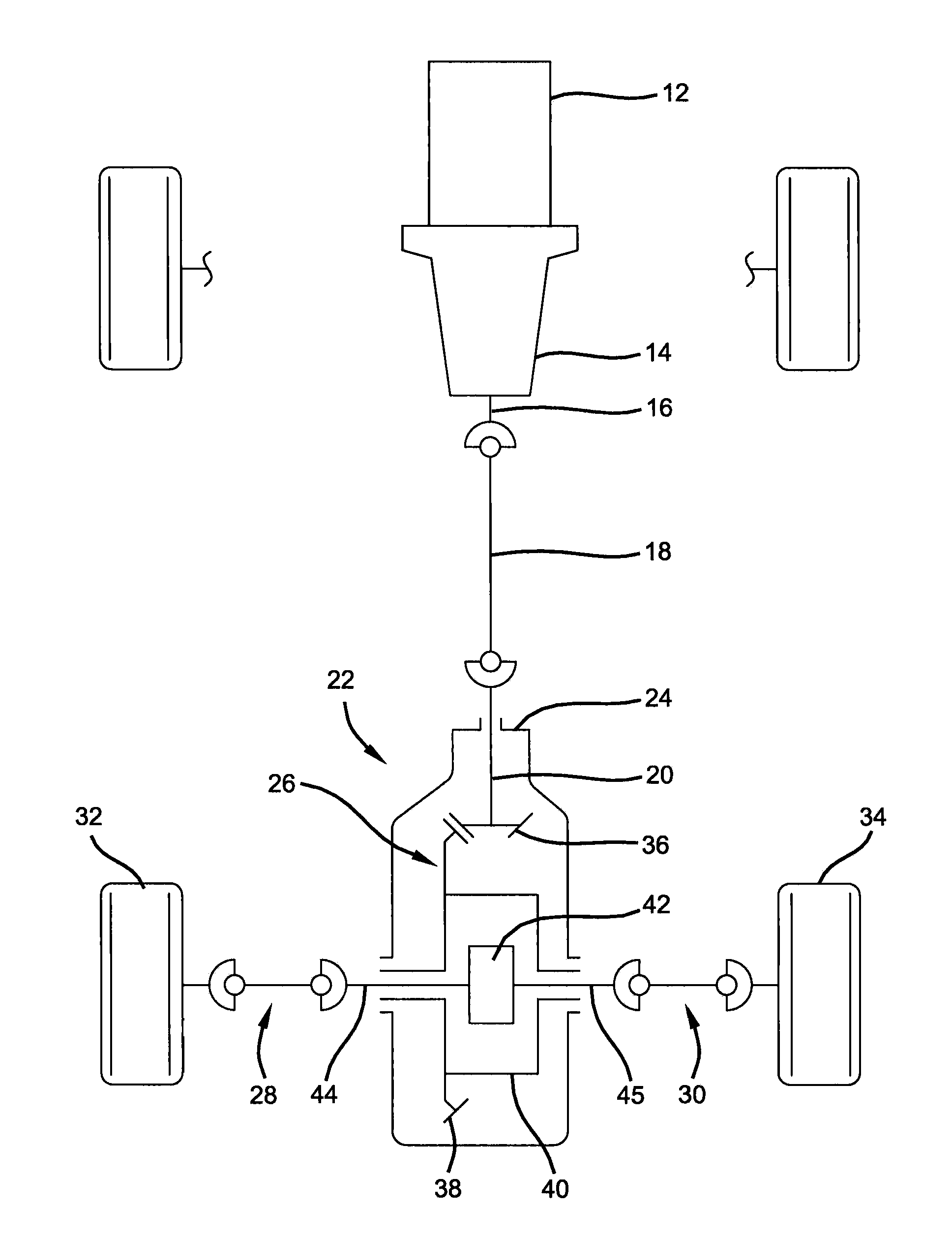
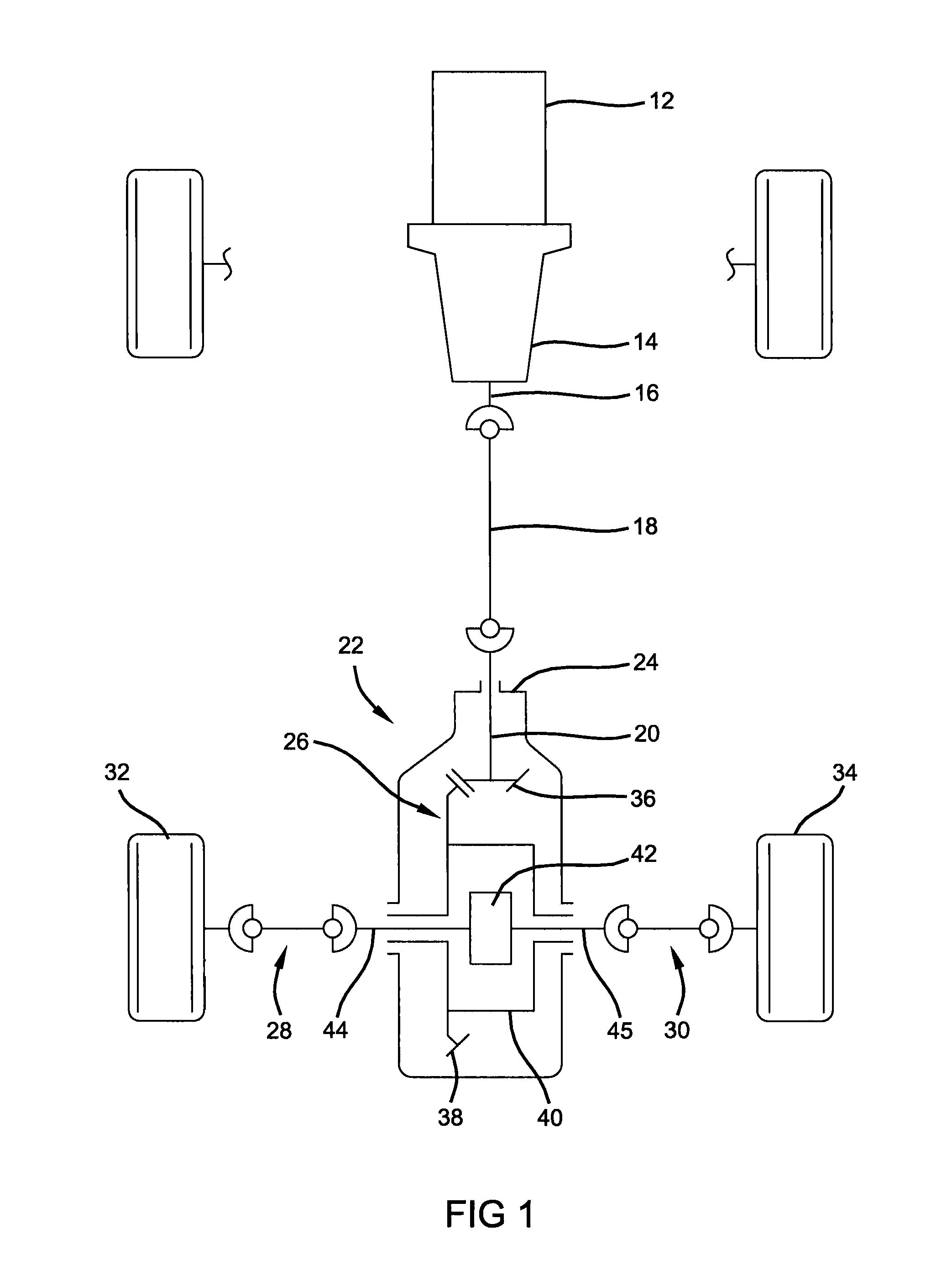
[0026]With initial reference to FIG. 1, a drivetrain 10 for an exemplary motor vehicle is shown to include an engine 12, a transmission 14 having an output shaft 16, and a propeller shaft 18 connecting output shaft 16 to a pinion shaft 20 of a rear axle assembly 22. Rear axle assembly 22 includes an axle housing 24, a differential assembly 26 rotatably supported in axle housing 24, and a pair of axleshaft assemblies 28 and 30, respectively, interconnected to left and right rear wheels 32 and 34, respectively. Pinion shaft 20 has a pinion gear 36 fixed thereto which drives a ring gear 38 that is fixed to a differentia...


PUM


Abstract

An axle assembly that includes a differential case which is rotatable about an axis, a pair of side gears that are disposed within the differential case, a spacer ring and a cross pin. The spacer ring is disposed between the side gears. The cross pin is fixed to one of the differential case and the spacer ring and extends through the spacer ring. The aperture in the spacer that receives the cross pin may be larger than the cross pin so that the spacer ring can control end play of the side gears independently of the cross pin.

Description

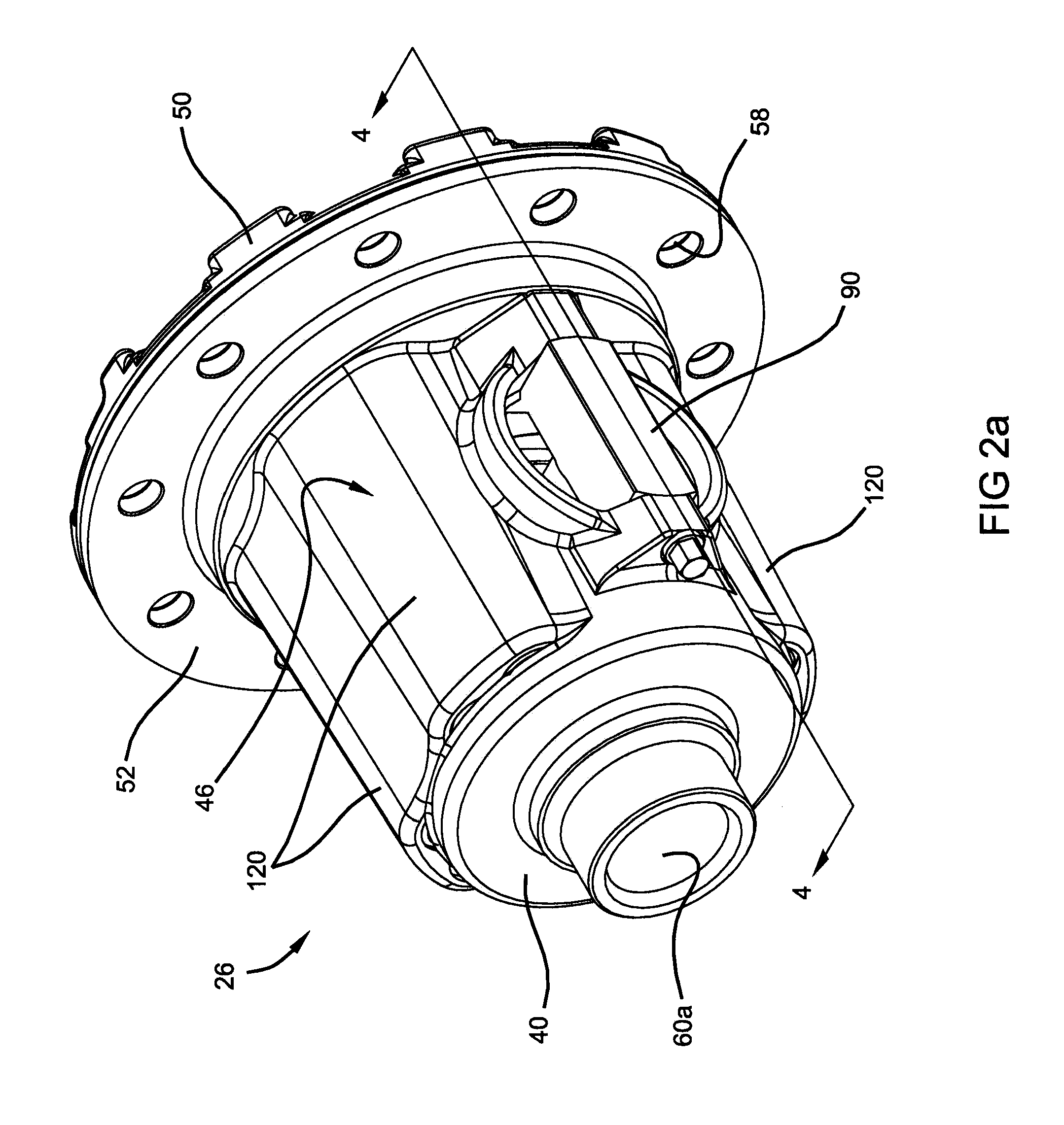
CROSS-REFERENCE TO RELATED APPLICATIONS[0001]This is a continuation-in-part of U.S. patent application Ser. No. 11 / 584,389 filed Oct. 20, 2006, which is a continuation of U.S. patent application Ser. No. 11 / 343,855 filed Jan. 31, 2006, now U.S. Pat. No. 7,147,585 which is a continuation of U.S. patent application Ser. No. 10 / 794,780 filed Mar. 5, 2004, now U.S. Pat. No. 7,022,041. The disclosures of the above applications are incorporated herein by reference.FIELD OF THE DISCLOSURE[0002]The present disclosure relates to differentials for use in automotive drivelines and, more particularly, to a spacer pin assembly for use in C-clip parallel-axis helical differentials which functions to provide independent control of side gear endplay and axleshaft endplay.BACKGROUND OF THE DISCLOSURE[0003]Differentials of the type used in automotive drivelines generally include a planetary gearset supported within a differential case to facilitate relative rotation (i.e., speed differentiation) betw...

Claims


Application Information

Patent Timeline
Patent Type & Authority Patents(United States)
IPC IPC(8): F16H3/74
CPCF16H48/11F16H48/10F16H48/08F16H2048/106
Inventor VALENTE, PAUL J.
Owner AMERICAN AXLE & MFG
Learn More