

Catheter Having Guidewire Channel
a technology of guidewires and catheters, applied in the field of catheters, can solve the problems of bifurcation, difficulty in insertion and placement of prosthetic devices, and difficulty in achieving the effect of guiding the guidewire through the main body prosthetic device, and avoiding the insertion of the side branch guidewire,
- Summary
- Abstract
- Description
- Claims
- Application Information
AI Technical Summary
Benefits of technology
Problems solved by technology
Method used
Image

Examples
example 1
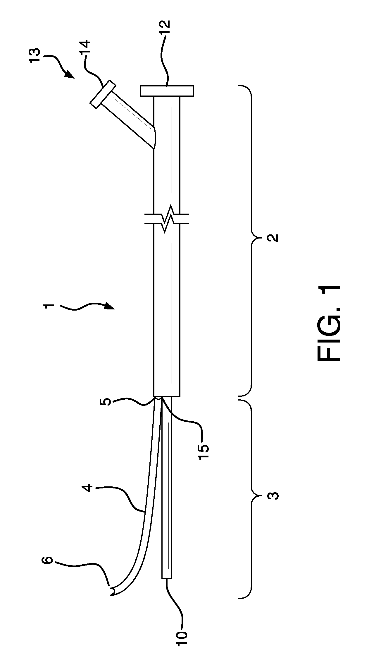
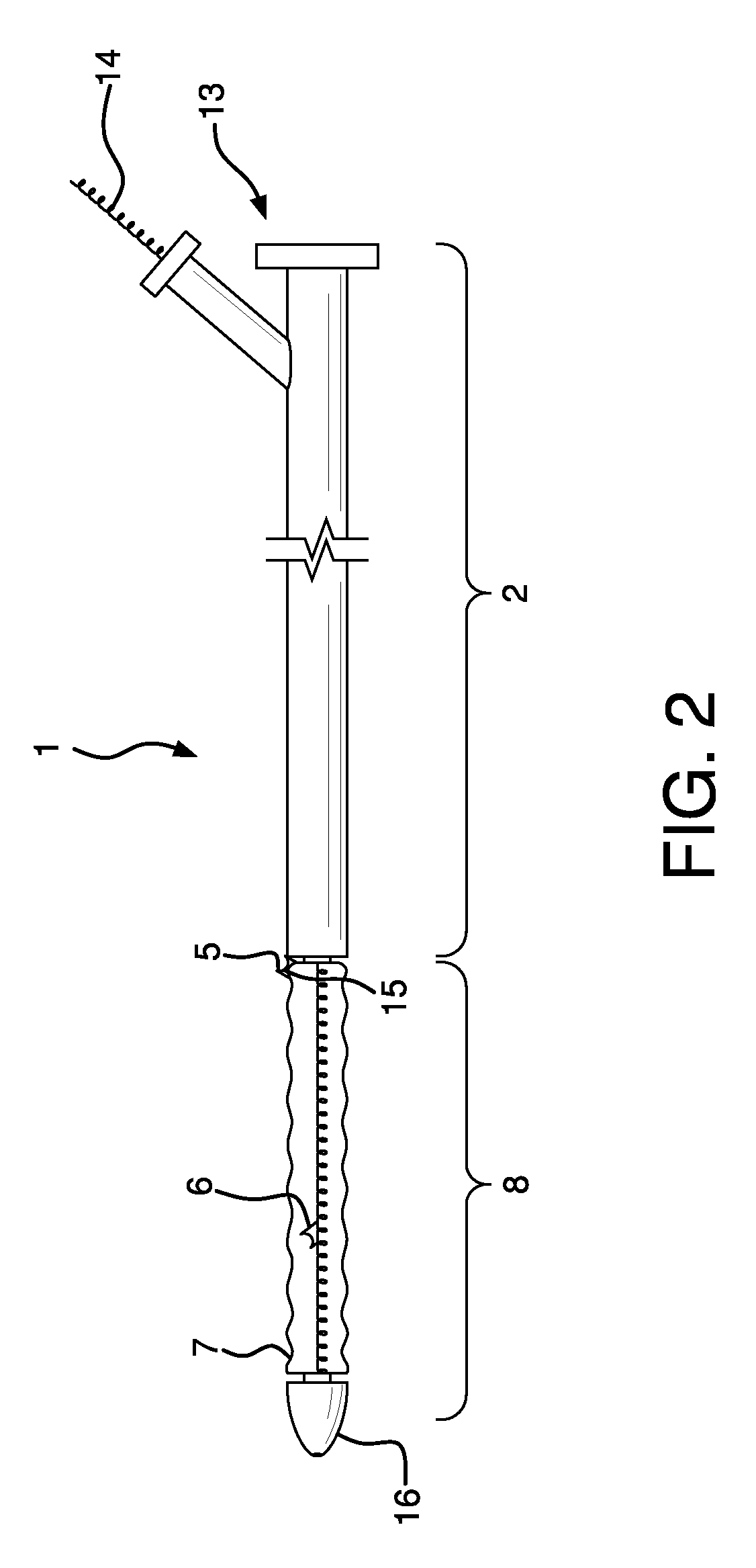
[0058]A catheter having an attached guidewire channel can be fabricated as follows:
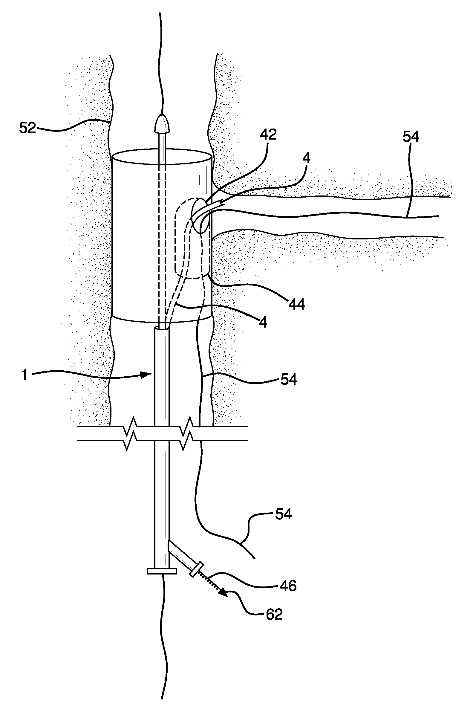
[0059]1) A self-expanding, main body stent graft can be provided having an outer diameter of 3.1 cm, a length of 15 cm and a graft wall thickness of about 0.005″. The graft material can be comprised of ePTFE and FEP and formed from an extruded and expanded thin walled tube that can be subsequently wrapped with ePTFE film. A nitinol wire having a diameter of about 0.0165″ can be helically wound to form a stent having an undulating, sinusoidal pattern. The formed, heat-treated stent can be placed onto the base graft. An additional film layer of ePTFE and FEP can be wrapped onto the stent and base graft to selectively adhere the stent to the graft.
[0060]2) The main body stent graft can have an internal side-branch support channel formed into the graft wall. Details relating to exemplary fabrication and materials used for an internal side branch support channel can be found in U.S. Pat. No. 6,645,242 to Q...
PUM
 Abstract
Description
Claims
Application Information