Transcutaneous charging device

a charging device and implantable technology, applied in electrotherapy, transportation and packaging, therapy, etc., can solve the problems of affecting the safety of patients, the implant may heat up faster than the surrounding tissue, and damage the surrounding tissue, so as to speed up the charging process and enhance the safety of patients

Active Publication Date: 2008-12-11
IMPULSE DYNAMICS NV
View PDF15 Cites 40 Cited by
  • Summary
  • Abstract
  • Description
  • Claims
  • Application Information

AI Technical Summary

Benefits of technology

[0008]An aspect of some embodiments of the invention relates to an implant and a transcutaneous charging devic

Problems solved by technology

If the user overestimates the available charge the result could be fatal, depending on the application.
One problem with using such a metal enclosure is that it may heat up as a result of eddy currents caused by a time-varying electromagnetic f

Method used


Image

  • Transcutaneous charging device
  • Transcutaneous charging device
  • Transcutaneous charging device

Examples


Embodiment Construction

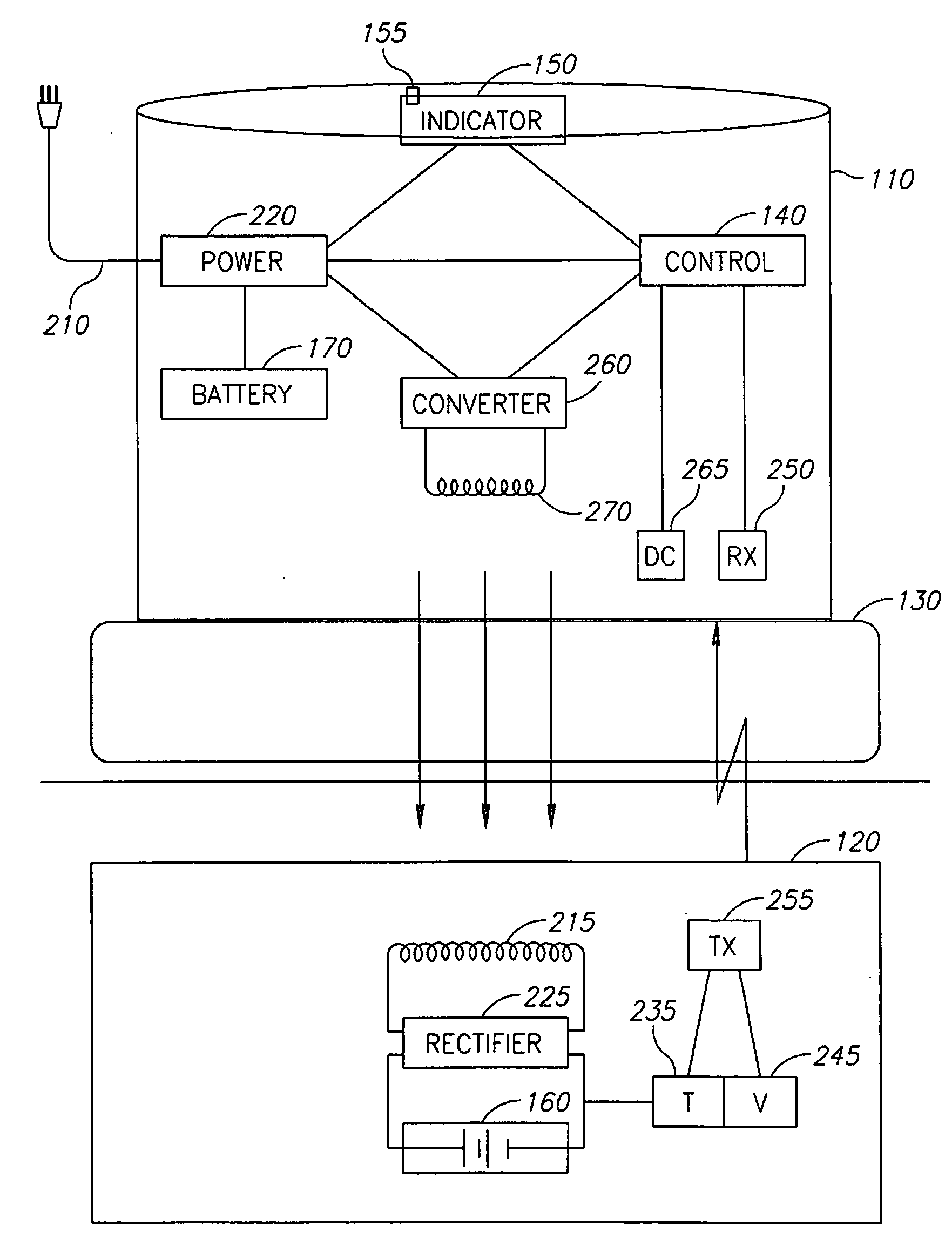
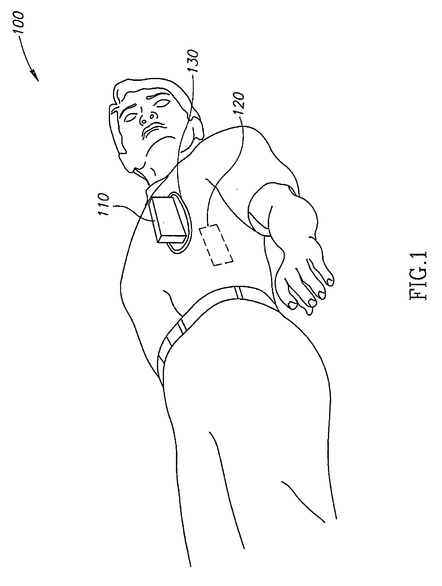
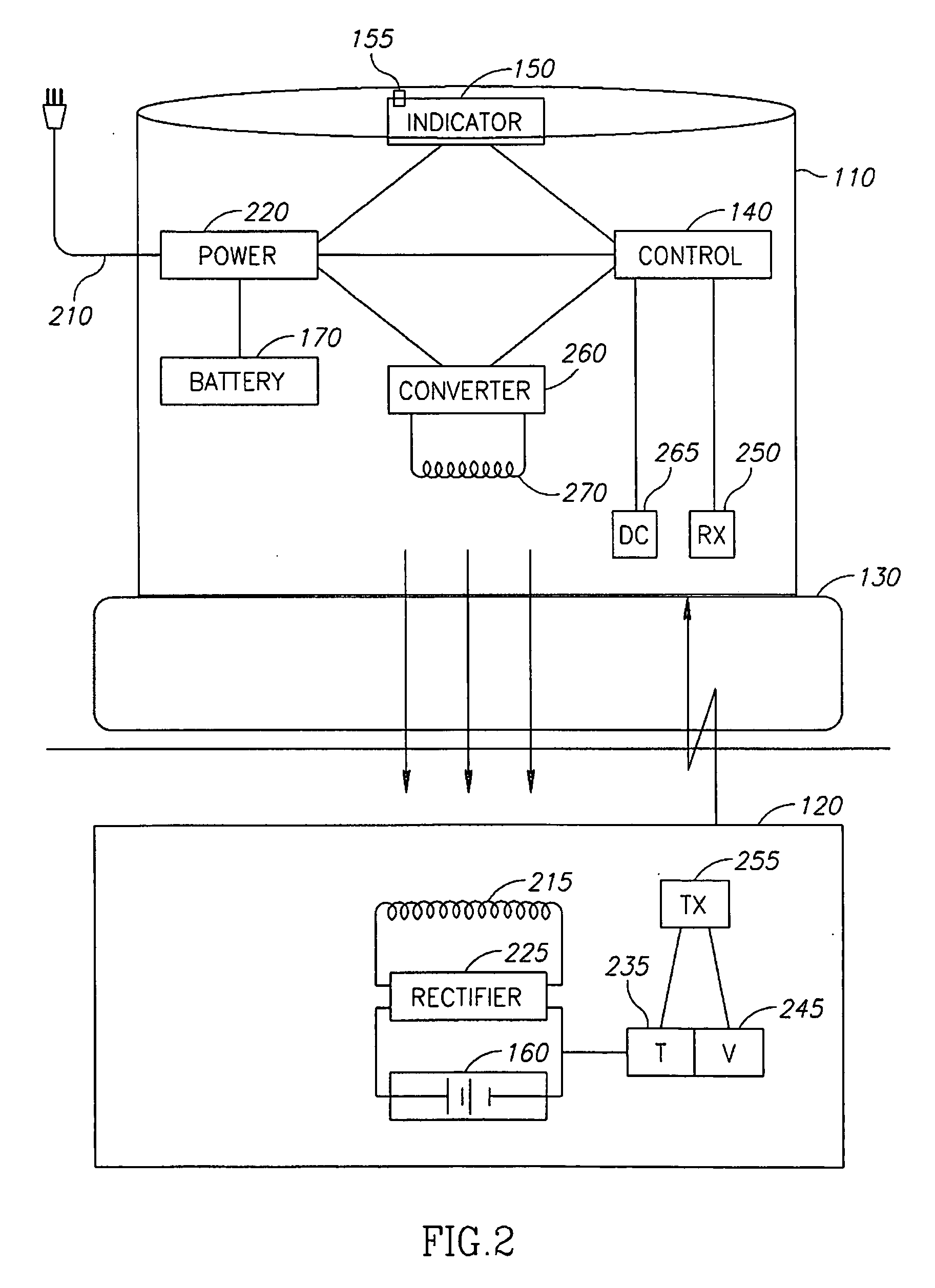
[0058]FIG. 1 is a schematic illustration of a transcutaneous charge system 100 comprising a charger 110 and an implant 120, for example a pacemaker, deployed according to an exemplary embodiment of the invention. Typically, implant 120 is implanted in a patient during a medical operation. In an exemplary embodiment of the invention, charger 110 is placed on the patient's skin facing implant 120 in order to transcutaneously recharge a power source in implant 120.

[0059]In an exemplary embodiment of the invention, charger 110 is placed on the skin in a location as close as possible to implant 120. In some embodiments of the invention, a separation is placed between charger 110 and the skin, for example a piece of material or a towel. The separation makes the touch of the charger more comfortable and protects the patient from heat in the charger. Optionally, a cooled pad 130 (e.g. a cooled water pad) is placed between the skin and charger 110 in order to alleviate the effect of heating ...


PUM


Abstract

A transcutaneous charging device for charging an implant comprising:
    • a power input;
    • a conversion circuit to convert power from said power input to transcutaneously charge said implant;
    • a control; and
    • an indication element;
    • wherein said control is programmed to initiate an indication using said indication element when it is time to charge said implant.

Description

RELATED APPLICATIONS[0001]This application claims the benefit of priority from U.S. Provisional Patent Application No. 60 / 924,920 filed on Jun. 5, 2007, the contents of which are incorporated by reference as if fully set forth herein.FIELD OF THE INVENTION[0002]The present invention relates to transcutaneous charging of an implantable medical device.BACKGROUND OF THE INVENTION[0003]It is common practice in the field of medicine to implant electronic devices inside the human body in order to overcome various problems, for example a pacemaker, a defibrillator or an infusion pump. Such devices require a power source for the device to monitor the body and optionally, perform a remedial function. For some devices, power for the device is supplied by a rechargeable battery that can be recharged transcutaneously so that additional operations on the patient are not needed in order to replenish the electrical power source.[0004]Some types of rechargeable batteries (e.g. Nickel-Cadmium) suffe...

Claims


Application Information

Patent Timeline
IPC IPC(8): H02J7/02
CPCH02J7/025A61N1/3787H02J50/90H02J50/80H02J50/10
Inventor PRUTCHI, DAVIDSPEHR, PAUL RICHARD
Owner IMPULSE DYNAMICS NV
Why Eureka
Try Eureka