Impeller

a technology of impeller and blade, which is applied in the direction of liquid fuel engine, machine/engine, reaction engine, etc., can solve the problems of poor mass uniformity of the parts of the impeller such as the annular plate or the blade distant from the central axis of the impeller, adversely affecting the effect and stability of the electronic device, etc., to achieve the effect of improving the balancing precision and being easy to manufactur

Inactive Publication Date: 2009-01-29
SUNONWEALTH ELECTRIC MACHINE IND
View PDF7 Cites 0 Cited by
  • Summary
  • Abstract
  • Description
  • Claims
  • Application Information

AI Technical Summary

Benefits of technology

[0008]Another object of the present invention is to provide a novel impeller that has improved balancing precision.
[0009]A further object of the present invention is to provide a novel impeller that can easily be manufactured.SUMMARY OF THE INVENTION
[0011]The impeller having such a structure can be formed at a smaller injection pressure to avoid deformation of the product. The smaller injection pressure maintains the quality stability of the products while avoiding the waste of materials. Even the areas in the mold cavity distant to the inlet port can be uniformly filled at the smaller injection pressure. The overall weight of the impeller is reduced. Furthermore, the impeller has improved mass uniformity and hence improved overall balancing precision.

Problems solved by technology

An excessively high temperature environment adversely affects the effects and stability of the electronic devices.
Thus, it is difficult to fill the molten plastic material into the mold cavity in a uniform manner, particularly in the areas distant to the inlet port.
As a result, the mass uniformity of the portions of the impeller such as the annular plate or the blades distant to the central axis of the impeller is poor.
Particularly, non-uniform distribution of the molten plastic material in the mold cavity tends to occur in the areas behind the bends in the mold cavity.
As a result, required mass uniformity throughout various portions of the impeller can not be obtained, leading to reduced overall balancing precision.

Method used


Image

  • Impeller
  • Impeller
  • Impeller

Examples


Embodiment Construction

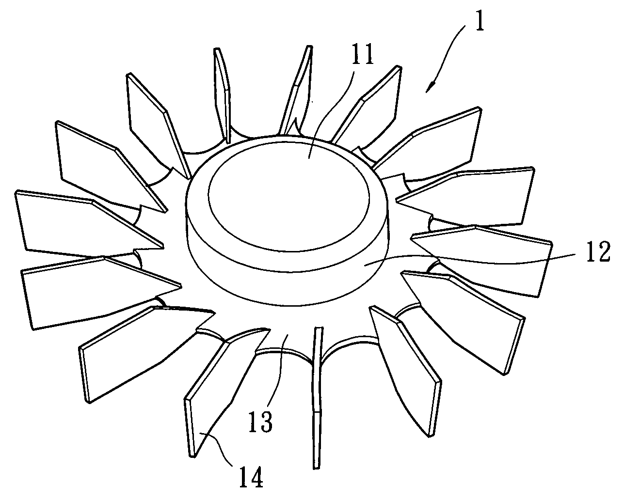
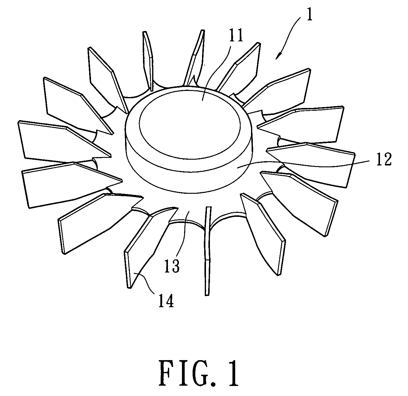
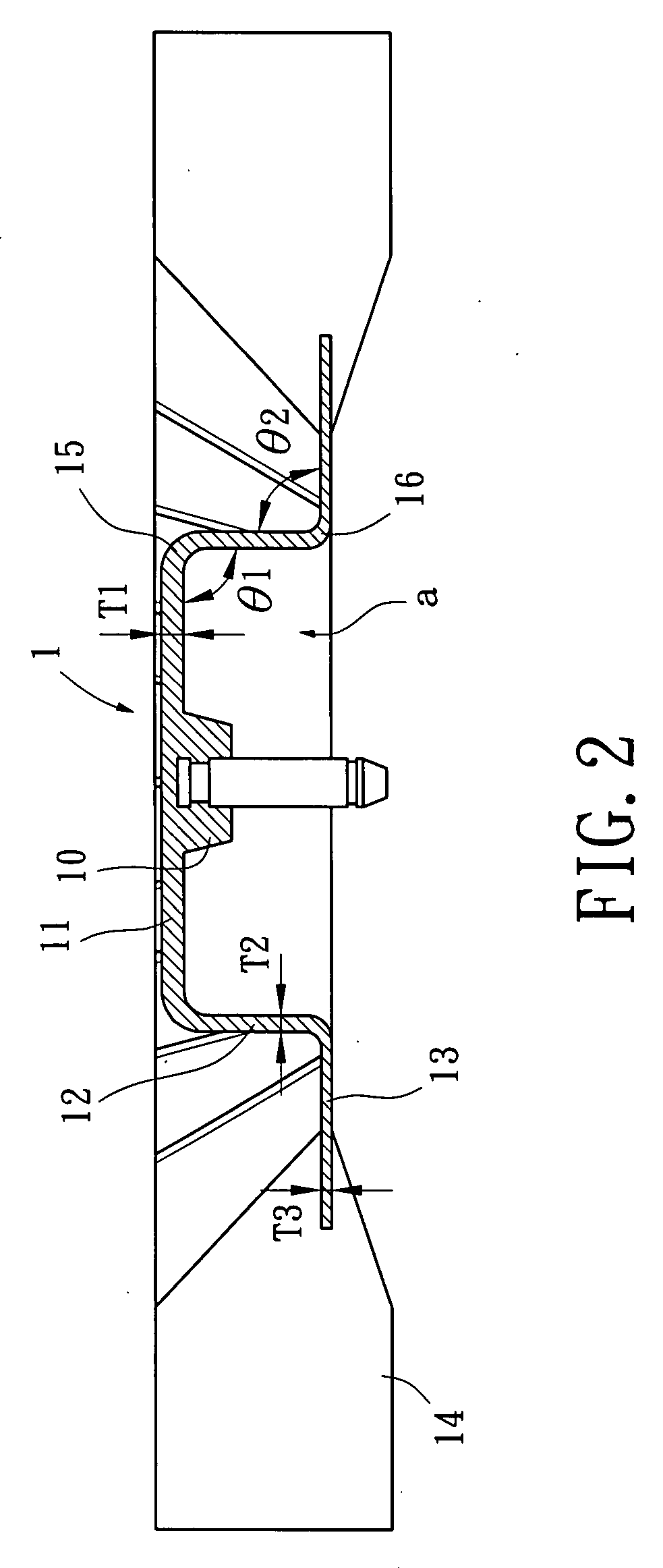
[0017]An impeller 1 of a first embodiment according to the preferred teachings of the present invention is shown in FIGS. 1-2. The impeller 1 includes a shaft base 10 defining a central axis about which the impeller 1 rotates. The impeller 1 further includes a plurality of portions and a plurality of bends. In the first embodiment shown, according to the distance to the shaft base 10, the plurality of portions correspond to a top portion 11 of a hub of the impeller 1 (i.e., the first portion), an annular wall 12 of the hub of the impeller 1 (i.e., the second portion), and an annular plate portion 13 (i.e., the third portion). Specifically, the top portion 11 of the hub extends radially outward from a circumference of the shaft base 10. The annular wall portion 12 of the hub extends from an outer circumference of the top portion 11 of the hub in a direction perpendicular to a general plane on which the top portion 11 lies. The top portion 11 and the annular wall portion 12 together d...


PUM


Abstract

An impeller includes a plurality of portions, a plurality of bends, and a plurality of blades. A substantial thickness of a portion is smaller than a substantial thickness of another portion more adjacent to a central axis of the impeller. Each bend is interconnected between two portions adjacent to each other. The blades are formed on the portion most distant to the central axis. The overall weight of the impeller is reduced. Furthermore, the impeller has improved mass uniformity and hence improved overall balancing precision.

Description

BACKGROUND OF THE INVENTION[0001]1. Field of the Invention[0002]The present invention relates to an impeller and, more particularly, the present invention relates to an impeller including a plurality of portions formed by injection molding in which a substantial thickness of a portion is smaller than a substantial thickness of another portion more adjacent to a central axis of the impeller to improve the balancing precision of the impeller.[0003]2. Description of Related Art[0004]The temperature results from operation of electronic devices becomes higher and higher while the effects of the electronic devices are enhanced. An excessively high temperature environment adversely affects the effects and stability of the electronic devices. Heat-dissipating units have, therefore, become one of the necessities of current electronic devices. Heat-dissipating devices generally include heat-dissipating fans having sizes matching with the volumes of the electronic elements in the electronic de...

Claims


Application Information

Patent Timeline
Patent Type & Authority Applications(United States)
IPC IPC(8): F01D5/14
CPCF04D29/30F04D29/281
Inventor HORNG, ALEX
Owner SUNONWEALTH ELECTRIC MACHINE IND
Why Eureka
Try Eureka