Illuminating apparatus for display device and display device having same

a technology of illumination apparatus and display device, which is applied in the direction of electric variable regulation, process and machine control, instruments, etc., can solve the problems of inability to drive parallel, increase the cost of downsizing, weight reduction, and cost reduction, so as to reduce the brightness gradient and reduce the concentration of noise and unwanted sounds. , the effect of reducing the brightness gradien

Active Publication Date: 2009-05-14
SHARP KK
View PDF8 Cites 3 Cited by
  • Summary
  • Abstract
  • Description
  • Claims
  • Application Information

AI Technical Summary

Benefits of technology

[0010]With this structure, compared with a structure in which all the capacitors of the illuminating apparatuses are disposed in the same position (see FIG. 8A), uneven distribution of stray capacitors through which a leakage current flows can be reduced, and the gradient of brightness can be made lower. In addition, concentrated occurrence of noise and sounding can also be reduced.
[0012]With this structure, since the stray capacitors through which a leakage current flows can be symmetrically located in the one position and the counter position, the brightness gradient of the illuminating apparatus, seen as a whole, is symmetrical between the one position and the counter position. This results in a lower gradient of brightness. In addition, since the stray capacitors through which a leakage current flows are alternately located in the one position and the counter position, concentrated occurrence of noise and unwanted sounds is prevented.
[0014]With this structure, the brightness gradient can be lowered more effectively, and the concentration of noise and unwanted sounds can be alleviated more effectively.

Problems solved by technology

Since typical cold-cathode tube lamps used as a light source for display devices have a non-linear negative impedance characteristic, they cannot be driven in parallel.
This, however, requires as many power supply circuits as cold-cathode tube lamps causing cost increases.
This is disadvantageous also in terms of downsizing, weight reduction, and cost reduction.

Method used


Image

  • Illuminating apparatus for display device and display device having same
  • Illuminating apparatus for display device and display device having same
  • Illuminating apparatus for display device and display device having same

Examples


Embodiment Construction

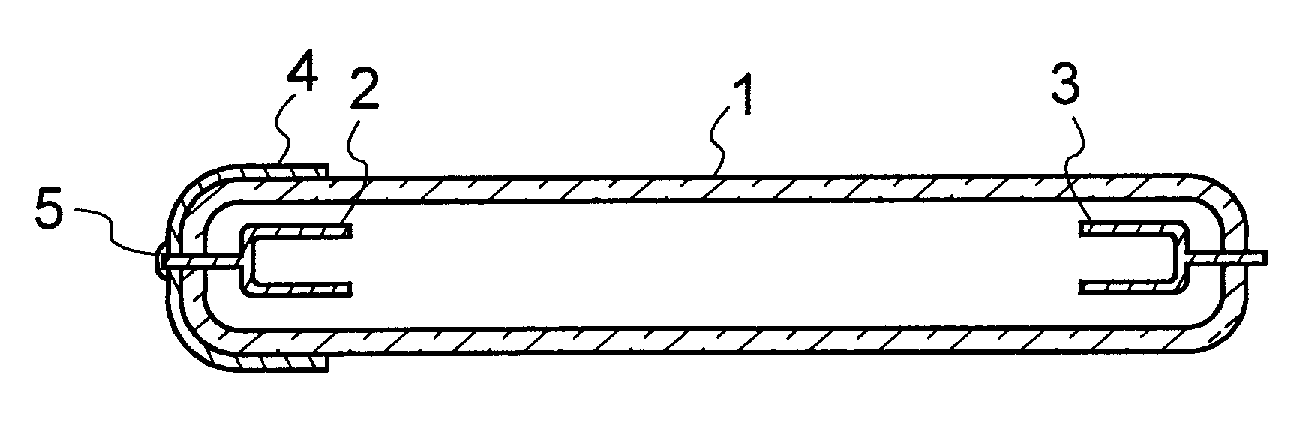
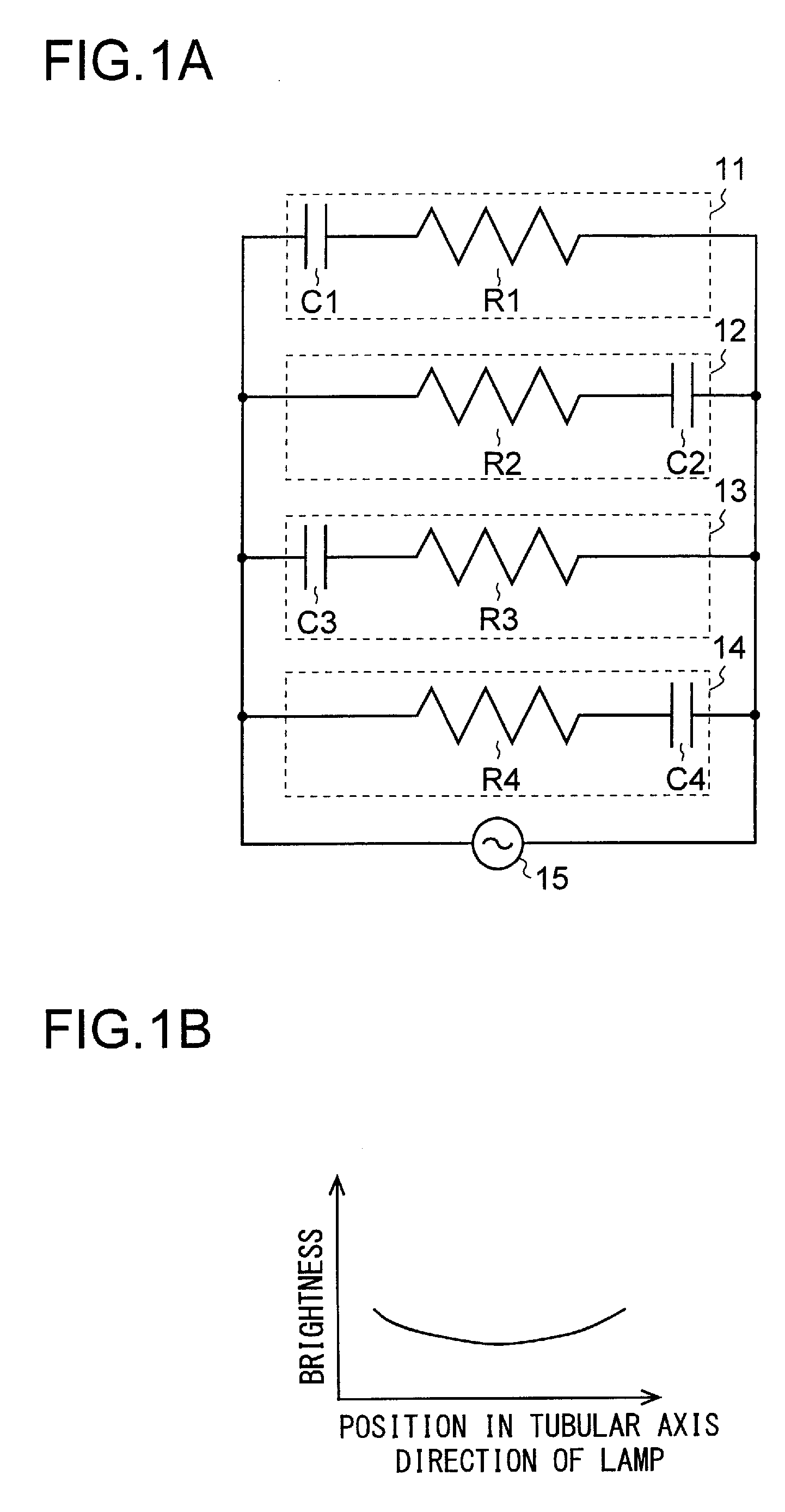
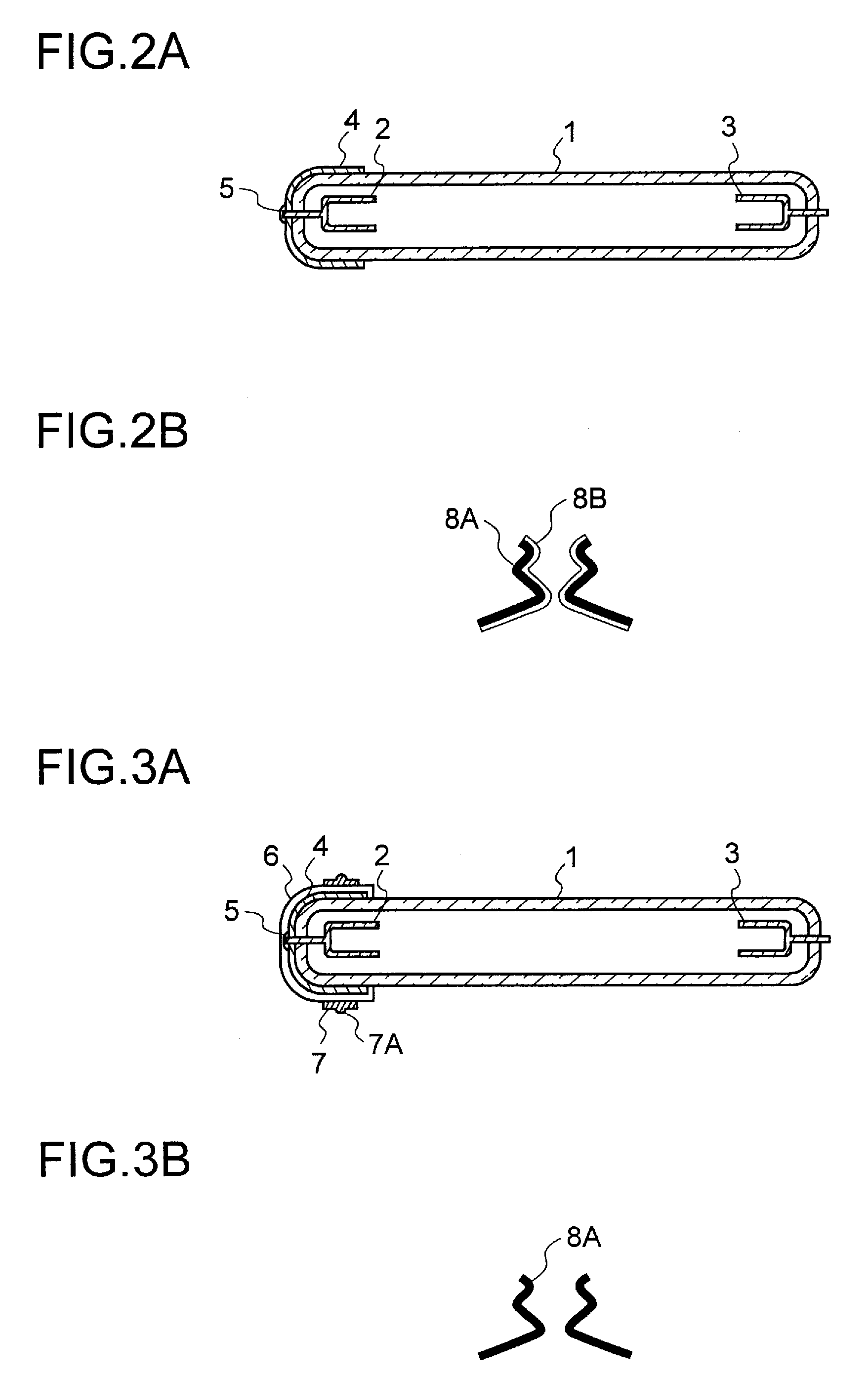
[0030]A description will be given of preferred embodiments of the present invention with reference to the drawings. An illuminating device for a display device according to a preferred embodiment of the present invention includes a plurality of illuminating units having: a first feeding member; a second feeding member; and a cold-cathode tube lamp to which power is supplied from a power supply apparatus via the first and second feeding members, an equivalent circuit of each of the illuminating units being a series combination of a negative resistor and a capacitor connected to an end of the negative resistor. In addition to the above described illuminating units, the illuminating apparatus for a display device according to a preferred embodiment of the present invention includes an optical sheet and an illuminating unit in which the first and second feeding members are provided and to the front surface of which the cold-cathode tube lamp is fitted. Here, the front surface of the ill...


PUM


Abstract

An illuminating apparatus used for a display device includes a plurality of illuminating parts, each of which comprises a first feeding member, a second feeding member, and a cold-cathode tube lamp that is fed by a power supply apparatus via the first and second feeding members. An equivalent circuit of each illuminating part is a series combination of negative resistor and a capacitor connected to an end of the negative resistor. The illuminating parts are arranged in such a manner that the capacitors of the cold-cathode tube lamps are alternate in position. This can reduce the brightness gradient for the position in the tubular axis direction of the lamp.

Description

BACKGROUND OF THE INVENTION[0001]1. Field of the Invention[0002]The present invention relates to an illuminating apparatus for a display device and a display device having the same, and specifically relates to a display device having a plurality of illuminating units each of which includes a first feeding member, a second feeding member, and a cold-cathode tube lamp to which power is supplied from a power supply apparatus via the first and second feeding members, the equivalent circuit of each of the illuminating units being a series combination of a negative resistor and a capacitor connected to an end of the negative resistor.[0003]2. Description of the Related Art[0004]Since typical cold-cathode tube lamps used as a light source for display devices have a non-linear negative impedance characteristic, they cannot be driven in parallel. Thus, power supply circuits are normally provided one for each cold-cathode tube lamp. This, however, requires as many power supply circuits as col...

Claims


Application Information

Patent Timeline
Patent Type & Authority Applications(United States)
IPC IPC(8): G05F1/00
CPCG02F2001/133612G02F1/133604G02F1/133612
Inventor TAKATA, YOSHIKI
Owner SHARP KK
Why Eureka
Try Eureka