Webbing winder

a winder and webbing technology, applied in the field of webbing winders, can solve the problems of preventing the movement of the restricting member the restricting member cannot reach the restriction position, and the restricting member cannot be moved to the restriction position, so as to achieve the effect of further miniaturization further saving of space, and enhancing the mountability of the rotary member

Active Publication Date: 2009-09-03
KK TOKAI RIKA DENKI SEISAKUSHO
View PDF10 Cites 24 Cited by
  • Summary
  • Abstract
  • Description
  • Claims
  • Application Information

AI Technical Summary

Benefits of technology

[0024]In the webbing winder according to the sixth aspect of the invention, the rotation detecting member has not only the function of actuating the locking member but also the function of being oscillated in the lock start direction with respect to the rotary member by the rotation of the rotary member. Therefore, the space can be further saved, the mountability on the rotary member can be further enhanced, and the rotary member can be further miniaturized. In addition, the cost can be further reduced.

Problems solved by technology

However, if a spool is rotated rapidly and slightly in the withdrawal direction in reaction immediately after the webbing belt is completely wound, the inertial member disposed in the lock gear accidentally meshes with the ratchet gear formed at the cover.
Therefore, basically (that is, in the case where the rotary member is not rotated in the withdrawal direction in reaction when the spool stops winding the webbing belt), the restricting member cannot be separated from the non-restriction position even if the rotary member is rotated in the withdrawal direction, so that the restricting member cannot reach the restriction position.
Therefore, even if the spool is rotated in the withdrawal direction normally or during the rapid deceleration of the vehicle, and accompanying this, the rotary member is rotated in the withdrawal direction, the restricting member cannot be moved to the restriction position.

Method used


Image

  • Webbing winder
  • Webbing winder
  • Webbing winder

Examples


first exemplary embodiment

[0031]

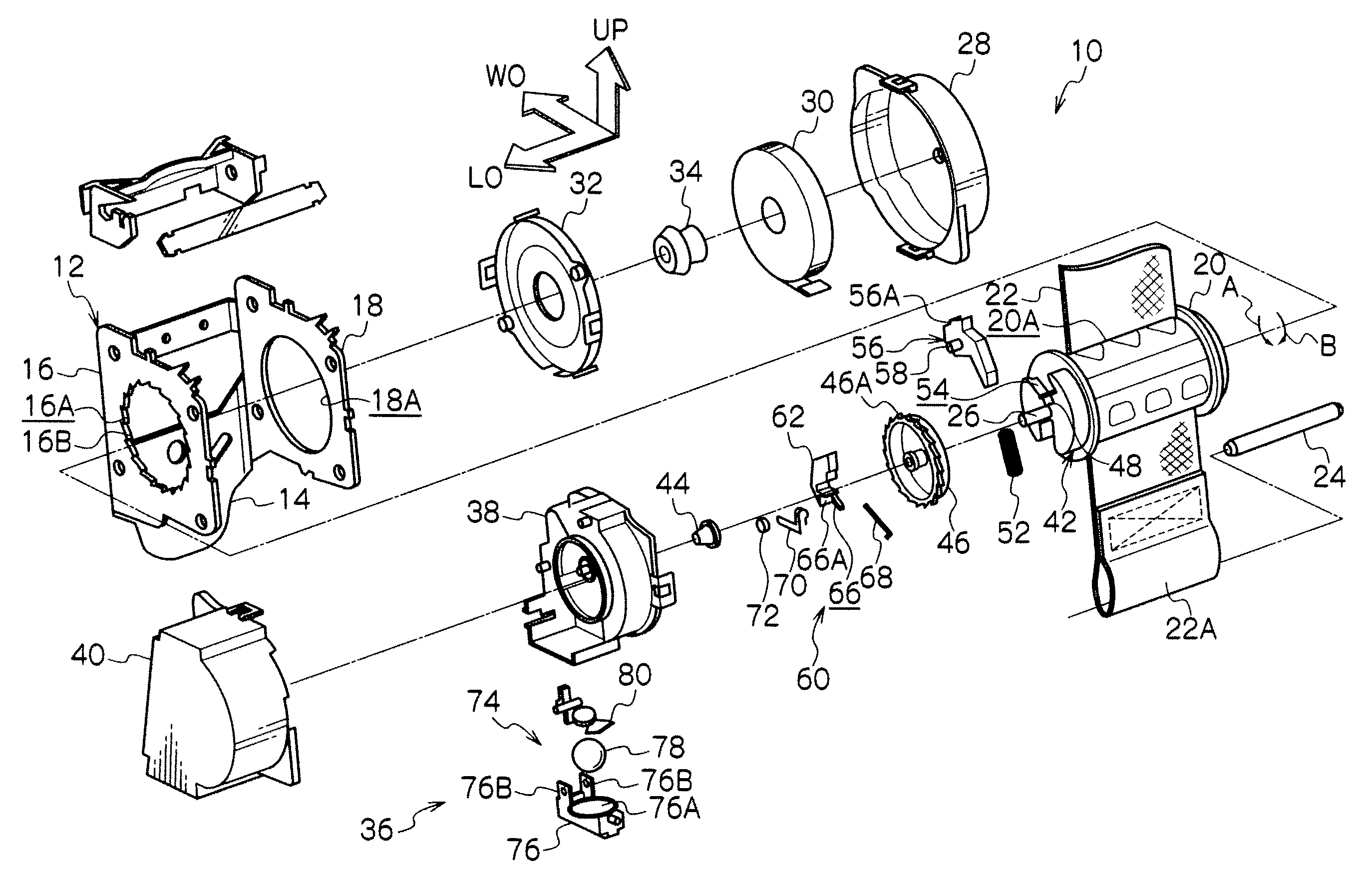
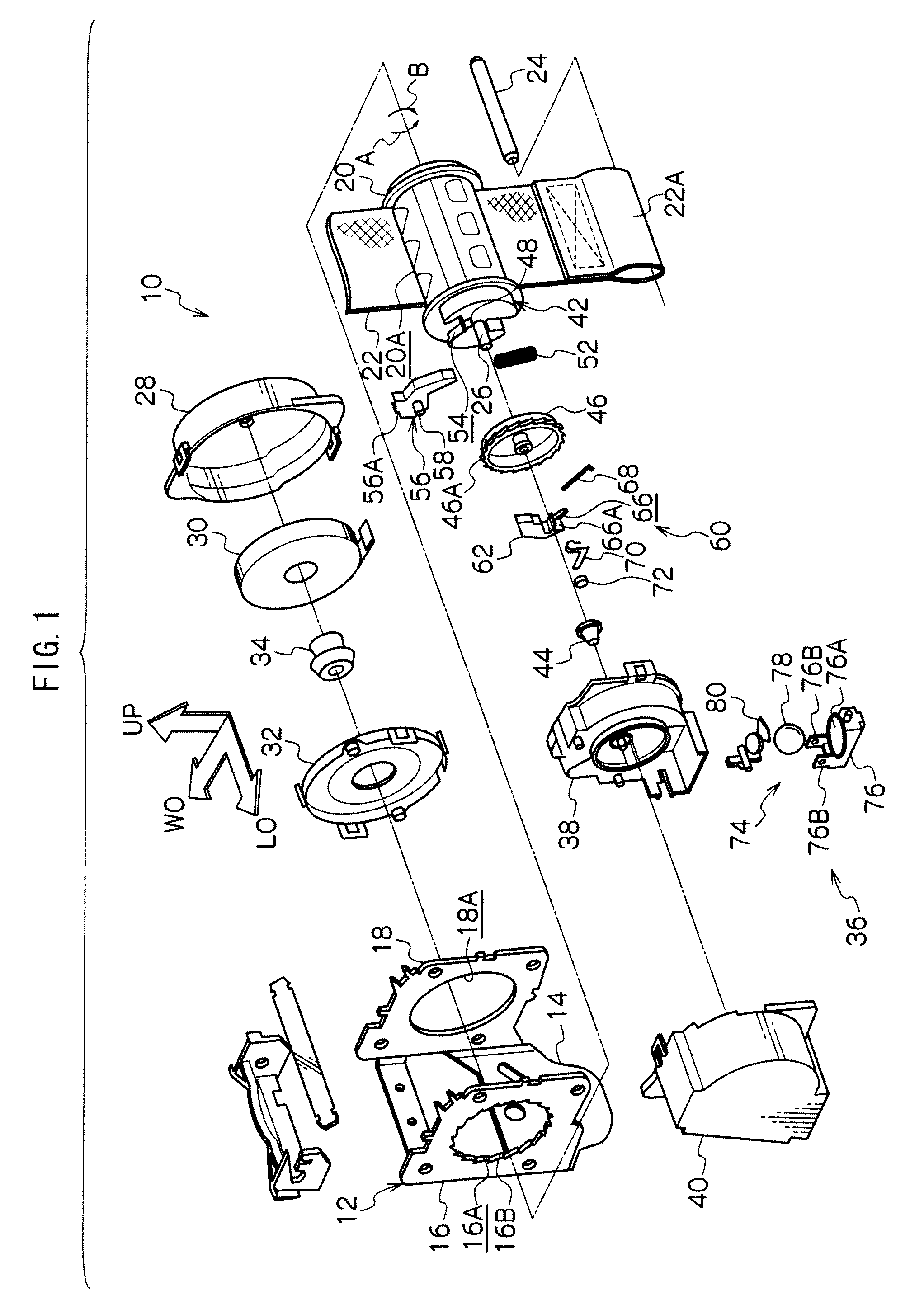
[0032]FIG. 1 is an exploded perspective view showing the entire configuration of a webbing winder 10 in a first exemplary embodiment according to the present invention. In FIG. 1, an arrow LO indicates one side in a lengthwise direction of a vehicle; another arrow WO indicates one side in a widthwise direction of the vehicle; and a further arrow UP indicates an upward direction.

[0033]As shown in FIG. 1, the webbing winder 10 is provided with a frame 12. The frame 12 includes, for example, a back plate 14 disposed substantially vertically in the widthwise direction of the vehicle. The back plate 14 is secured to a chassis in the vicinity of, for example, a lower end of a center pillar of the vehicle via tightening means such as a bolt, so that the webbing winder 10 is installed to the chassis. A leg plate 16 is bent toward the other side in the widthwise direction of the vehicle from one side end in the lengthwise direction of the vehicle of the back plate 14 whereas another le...

second exemplary embodiment

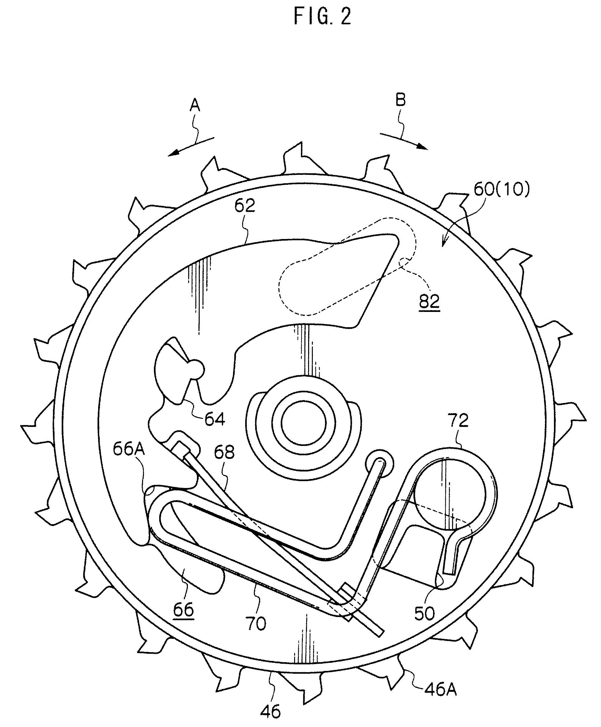
[0069]FIG. 4 is a front view showing essential parts of a webbing winder 100 in a second exemplary embodiment according to the invention.

[0070]The webbing winder 100 is configured in a manner substantially similar to that in the above-described first exemplary embodiment except points below.

[0071]In the webbing winder 100, a rotation detecting mechanism 60 is provided with a W pawl 102 serving as an engaging member (a meshing member) and an inertia mass 104 serving as a rotation detecting member in place of the W pawl 62 in the above-described first exemplary embodiment, wherein the W pawl 102 and the inertia mass 104 are arranged in a radial direction of a V gear 46.

[0072]The W pawl 102 is pivotably supported by a pin 106 formed at the V gear 46 at a position displaced from an axis of a support shaft 26 so as to be able to oscillate within a predetermined range on an axis parallel to the support shaft 26. The W pawl 102 is configured such that its oscillation brings one end thereof...


PUM


Abstract

In a webbing winder, when a webbing belt is wound around a spool, a V gear is rotated in a winding direction together with a W pawl, a friction spring, and a contact member, thereby generating a frictional force between the contact member and a sensor holder. As a consequence, the friction spring and the contact member are located at a restriction position, so that the friction spring engages with an engaging surface of the W pawl. Therefore, even if the spool and the V gear are rapidly and slightly rotated in a withdrawal direction in reaction when the webbing belt is completely wound by the spool, the W pawl cannot mesh with a ratchet gear formed at the sensor holder due to the restriction of oscillation of the W pawl, thus preventing any end lock.

Description

CROSS-REFERENCE TO RELATED APPLICATION[0001]This application claims priority under 35 USC 119 from Japanese Patent Application No. 2008-49395, the disclosures of which is incorporated by references herein.BACKGROUND[0002]1. Technical Field[0003]The present invention relates to a webbing winder which winds a webbing belt for restraining a body of a passenger.[0004]2. Related Art[0005]As disclosed in, for example, Japanese Patent Application Laid-open (JP-A) No. 5-193441, a webbing winder constituting a seat belt device for a vehicle is provided with a lock mechanism which restricts rotation of a reel shaft in a withdrawal direction during rapid deceleration of the vehicle. A lock gear constituting the lock mechanism disclosed in JP-A No. 5-193441 can be relatively rotated coaxially with the reel shaft. When the reel shaft is rotated relatively to the lock gear in the withdrawal direction, teeth of each of a main pawl and a backup pawl mesh with inner teeth formed on both side walls o...

Claims


Application Information

Patent Timeline
Patent Type & Authority Applications(United States)
IPC IPC(8): B60R22/38B65H75/30B65H75/44B65H75/48B60R22/34
CPCB60R2022/3419B60R22/41
Inventor AIHARA, KAZUHIKOSUMIYASHIKI, AKIRA
Owner KK TOKAI RIKA DENKI SEISAKUSHO
Why Eureka
Try Eureka