Image processing apparatus and method for the same

Active Publication Date: 2010-04-08
CANON KK
View PDF5 Cites 8 Cited by
  • Summary
  • Abstract
  • Description
  • Claims
  • Application Information

AI Technical Summary

Benefits of technology

[0013]Exemplary embodiments of the present invention are directed to a technique capable of reducing a burden in calculations for detecting an imaging object pattern and capable of maintaining accuracy in detection of the imaging object pattern.

Problems solved by technology

However, according to the technique discussed in Japanese Patent Application Laid-Open No. 2007-25899, a burden in calculation processing increases if the system generates a plurality of reduced images from an input image on a frame-by-frame basis and performs matching between a predetermined imaging object pattern and the template.
In this case, for example, if a zoomed-up image of a predetermined imaging object is captured by a camera, the system may not perform tracking using panning and tilting functions when the predetermined imaging object exits from the frame between non-processed frames.
However, the imaging object may not be captured in a detection area if a moving speed of the imaging object is inappropriate.
Further, in a zoom-up operation of the camera, or in a situation where a distance between the imaging object and the camera becomes shorter, the imaging object may not be detected based on only the detection at or near the coordinate position of the previous detection frame.
However, this technique is only effective in an operation for tracking an imaging object that has been captured in the input image and cannot be used in a situation where the distance between the imaging object and the camera is variable.
Accordingly, detection accuracy deteriorates when the distance between the imaging object and the camera is changed.

Method used


Image

  • Image processing apparatus and method for the same
  • Image processing apparatus and method for the same
  • Image processing apparatus and method for the same

Examples


Embodiment Construction

[0027]Various exemplary embodiments, features, and aspects of the present invention will now be herein described in detail below with reference to the drawings. It is to be noted that the relative arrangement of the components, the numerical expressions, and numerical values set forth in these embodiments are not intended to limit the scope of the present invention.

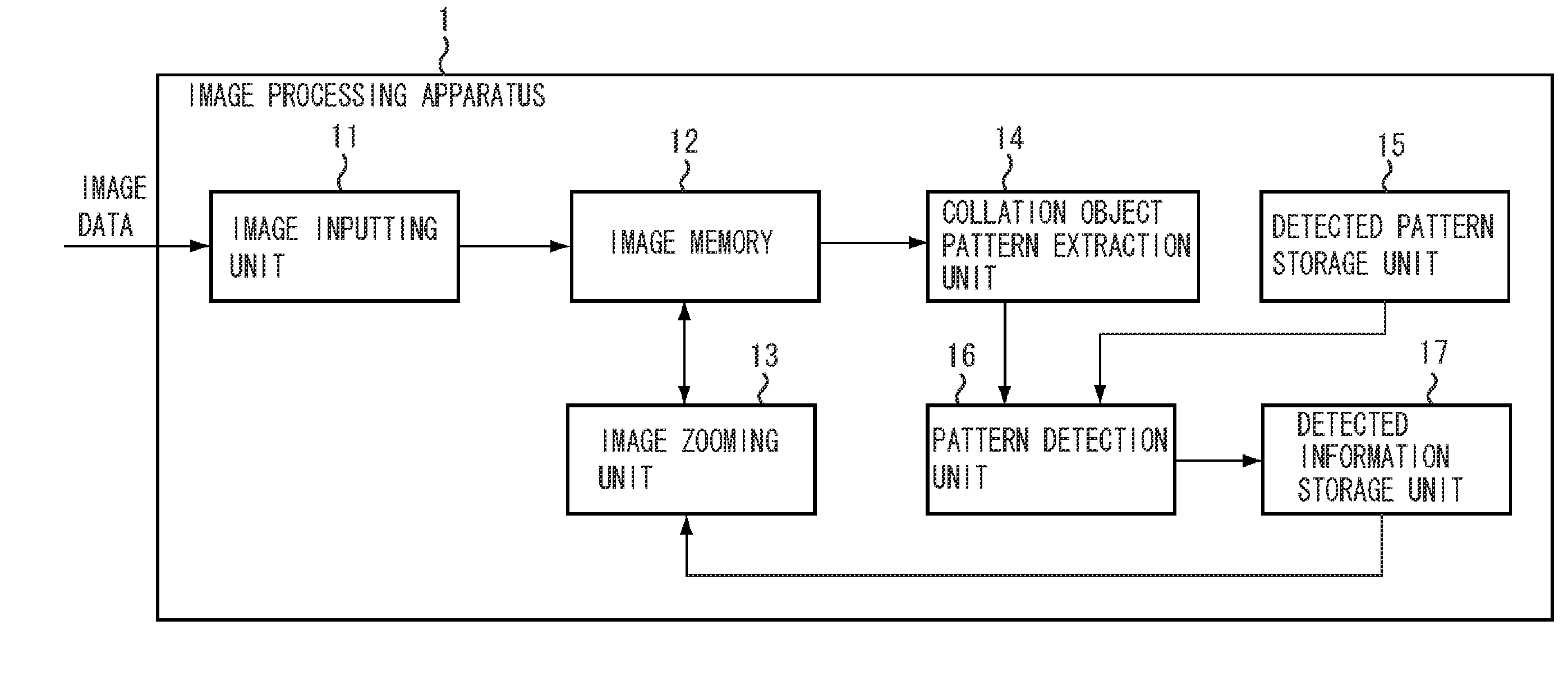
[0028]FIG. 1 is a block diagram illustrating an example of the configuration of an image processing apparatus 1 according to an exemplary embodiment of the present invention. First, the configuration of the image processing apparatus 1 according to the present exemplary embodiment is described below.

[0029]In FIG. 1, an image inputting unit 11 receives image data. The image inputting unit 11 has a decoding processing function for receiving image data that may be conformable to a specific communication method and compatible with a marker code-attached protocol or compression processed image data such as Joint Photographic E...


PUM


Abstract

An image processing apparatus can detect a predetermined target object from image data. The image processing apparatus includes an image zooming unit configured to generate a plurality of pieces of zoomed image data that are mutually different in magnification from the image data input by an image inputting unit, a detection unit configured to extract a partial area from the plurality of pieces of zoomed image data generated by the image zooming unit, and detect the predetermined target object by performing collation to determine whether the extracted partial area coincides with a detection pattern stored in a detected pattern storage unit, and a detected information storage unit configured to store detection information including magnification information of the zoomed image data from which the predetermined target object is detected by the detection unit. In a case where the detection information is stored in the detected information storage unit, the image zooming unit determines a magnification of the zoomed image data based on the detection information and generates at least one piece of zoomed image data whose total number is smaller compared to a case where the detection information is not stored.

Description

BACKGROUND OF THE INVENTION[0001]1. Field of the Invention[0002]The present invention relates to image processing, and more particularly to a technique capable of detecting an imaging object pattern from a moving image.[0003]2. Description of the Related Art[0004]Conventionally, an image processing method which can automatically detect a predetermined imaging object pattern from a moving image has been discussed and the method can be used to determine, for example, a human face or the like. This kind of image processing method can be used in a video conference, a monitoring system, or the like.[0005]Such techniques that can be used to detect a predetermined imaging object pattern from an image are, for example, discussed in Japanese Patent Application Laid-Open No. 2007-25899, Japanese Patent Application Laid-Open No. 2004-171490, and Japanese Patent Application Laid-Open No. 2003-235035 according to which the predetermined imaging object pattern can be detected using a template mat...

Claims


Application Information

Patent Timeline
IPC IPC(8): G09G5/00
CPCG09G2340/045G09G5/391
InventorNAGAMASA, YOSHINOBU
OwnerCANON KK